


17
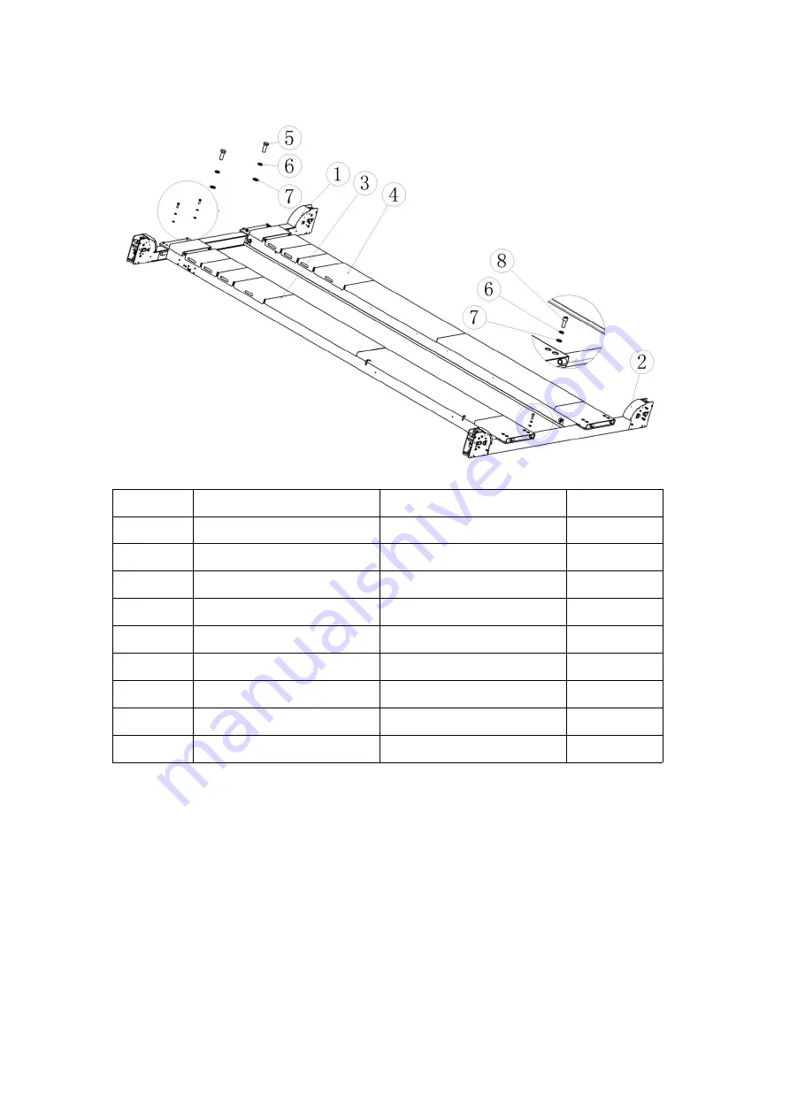
3.5The diagram after the platform is connected to the beam is shown below
::
NO.
ITEM
SPEC
QTY
1
Main beam
1
2
Auxiliary beam
1
3
Main platform
1
4
Auxiliary platform
1
5
Outer hexagon bolt
M16*45
8
6
Spring pad
φ16
16
7
Flat pad
φ16
16
8
Socket head cap screws
M16*45
8
Note that after the platform and the beam are connected by bolts, do not tighten them
in advance. Tighten the bolts after connecting and adjusting with the post part later.
3.5 Packing disassembly and installation of the post:
Remove the top cover of the column, take out the mechanical lock bar, place the
four columns to the corresponding positions of the beam, and insert the mechanical
lock bar between the mechanical lock and the safety lock of the beam, as shown in the
figure below.
:
Содержание SXJS4019A
Страница 8: ...7 Main platform Steel Rope in Rear position Fig2 Main platform Steel Rope in Rear position Fig3 ...
Страница 9: ...8 Top view of steel rope general arrangement ...
Страница 28: ...27 The electrical schematic and wiring diagram of standard electrical four post lift as above figures ...
Страница 43: ...10 2 2 Warning mark ...
Страница 55: ...22 ...
Страница 56: ...23 Chapter 7 Hydraulic System 7 1 Hydraulic pressure principle drawing ...
Страница 60: ...29 ...
Страница 61: ...30 ...
Страница 62: ...31 ...
Страница 63: ...32 ...
Страница 64: ...33 ...
Страница 65: ...34 ...


