7
VARIABLE FREQUENCY DRIVES
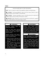
Do not leave VFDs unattended in
hand mode or manual bypass.
Damage to personnel or equipment
can occur if left unattended. When in
hand mode or manual bypass mode
VFDs will not respond to controls or
alarms.
WARNING
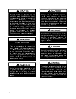
GROUNDING REQUIRED
All field installed wiring must be
completed by qualified personnel.
Field installed wiring must comply
with NEC/CEC, local and state
electrical code requirements. Failure
to follow code requirements could
result in serious injury or death.
Provide
proper
unit
ground
in
accordance
with
these
code
requirements.
WARNING
During installation, testing, servicing
and troubleshooting of the equipment
it may be necessary to work with live
electrical
components.
Only
a
qualified
licensed
electrician
or
individual properly trained in handling
live
electrical
components
shall
perform these tasks.
Standard
NFPA-70E,
an
OSHA
regulation requiring an Arc Flash
Boundary to be field established and
marked for identification of where
appropriate
Personal
Protective
Equipment (PPE) be worn, should be
followed.
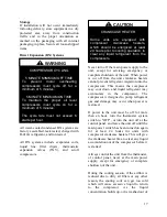
WARNING
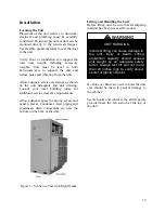
UNIT HANDLING
To prevent injury or death lifting
equipment capacity shall exceed unit
weight by an adequate safety factor.
Always test-lift unit not more than 24
inches high to verify proper center of
gravity lift point to avoid unit damage,
injury or death.
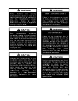
WARNING
ROTATING COMPONENTS
Unit contains fans with moving parts
that can cause serious injury. Do not
open door containing fans until the
power
to
the
unit
has
been
disconnected and fan wheel has
stopped rotating.
WARNING
Electric motor over-current protection
and overload protection may be a
function of the Variable Frequency
Drive to which the motors are wired.
Never defeat the VFD motor overload
feature. The overload ampere setting
must not exceed 115% of the electric
motors FLA rating as shown on the
motor nameplate.
CAUTION
Failure to properly drain and vent
coils when not in use during freezing
temperature may result in coil and
equipment damage.
CAUTION
Содержание SA-028
Страница 2: ......
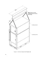
Страница 20: ...20 Figure 2 One Piece Single Unit Lifting Details...
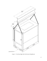
Страница 21: ...21 Figure 3 Two Piece Single Unit Coil Section Lifting Details...
Страница 22: ...22 Figure 4 Two Piece Single Unit Fan Section Lifting Details...
Страница 23: ...23 Figure 5 One Piece Dual Unit Lifting Details...
Страница 24: ...24 Figure 6 Two Piece Dual Unit Coil Section Lifting Details...
Страница 25: ...25 Figure 7 Two Piece Dual Unit Fan Section Lifting Details...
Страница 27: ...27 Figure 8 Dual unit without splices and before being bolted together Figure 9 Dual Unit Assembly Details...
Страница 28: ...28 Figure 10 Dual unit with splices after being bolted together...
Страница 63: ...63...


