42
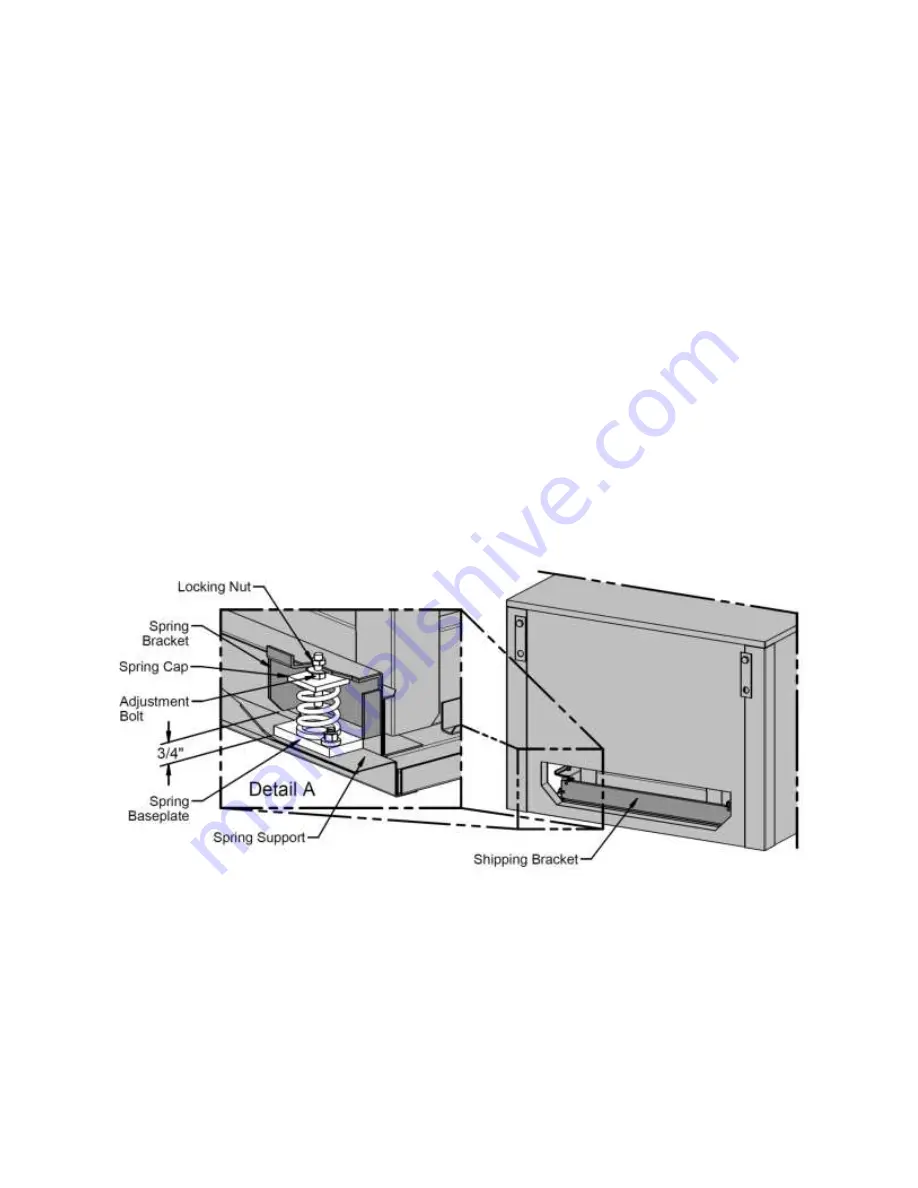
Fan assemblies are equipped with spring
isolators in the fan section for vibration
attenuation.
Prior to shipment the isolators are set in the
lock down position to protect the unit during
transit.
Once the unit is set into place it is important
that all of the isolators are adjusted out of
the shipping position and the shipping
material is discarded before the unit is put
into operation.
Remove all six screws from each shipping
bracket and discard brackets.
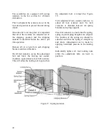
On all four isolators, secure the adjustment
bolt and rotate the locking nut counter
clockwise approximately four full rotations.
This will allow the locking nut to spin when
the adjustment bolt is turned (See Figure
17).
Turn adjustment bolt counter-clockwise to
adjust all four isolators until 3/4 inch
clearance is obtained between all spring
brackets and spring supports.
Check all isolators to ensure that the spring,
spring cap and spring baseplate are aligned.
The position of the spring cap should be
adjusted such that the spring is straight up
and down. Adjustments can be made by
applying horizontal pressure to the locking
nut.
Individually tighten all four locking nuts
while the adjustment bolts are held in
position.
Figure 17 - Spring Isolation
Содержание SA-028
Страница 2: ......
Страница 20: ...20 Figure 2 One Piece Single Unit Lifting Details...
Страница 21: ...21 Figure 3 Two Piece Single Unit Coil Section Lifting Details...
Страница 22: ...22 Figure 4 Two Piece Single Unit Fan Section Lifting Details...
Страница 23: ...23 Figure 5 One Piece Dual Unit Lifting Details...
Страница 24: ...24 Figure 6 Two Piece Dual Unit Coil Section Lifting Details...
Страница 25: ...25 Figure 7 Two Piece Dual Unit Fan Section Lifting Details...
Страница 27: ...27 Figure 8 Dual unit without splices and before being bolted together Figure 9 Dual Unit Assembly Details...
Страница 28: ...28 Figure 10 Dual unit with splices after being bolted together...
Страница 63: ...63...


