background image

© CMS Magnetics 2007, 2008 

Confidential 

9

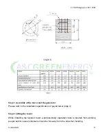
9.  Arrange the three blades on the hub, and then put on the press pad. Slide the screws 

into the holes and put on the nuts. Please make sure that the blade edge faces into the 

clockwise-rotating direction. 


Before tightening the nuts, please make sure the 3 blades are evenly installed by 

measuring the distance between the blade tips. (refer to Graph 5 on the following page) 


L1=L2=L3 (Tol/- 5mm or 1/8”) 


Содержание PowerMax+ 2000GT

Страница 1: ...INSTALLATION MANUAL 2000GT Grid Tie Wind Turbine 1108 Summit Avenue Suite 8 Plano TX 75074 866 WND PWRD www acgreenenergy com...

Страница 2: ...Output Graphs 4 Installation Specifications Guyed Tower 5 Installation Specifications Tapered Tower 11 Connection of the Charger Controller 12 Connection of Storage Batteries 13 Electric Wiring 14 Ma...

Страница 3: ...CMS Magnetics 2007 2008 Confidential 3 Parts List Please inspect all packaging crates contact your PowerMax reseller if there is any damage or missing parts...

Страница 4: ...Rated Power W 2000 Peak Power W 2500 Rotor Diameter ft 10 5 OUTPUT POWER 0 500 1000 1500 2000 2500 3000 3500 4000 7 9 13 16 19 20 22 25 26 29 31 33 36 38 40 Average Wind Speed mph Output Power W MONT...

Страница 5: ...en soil water erosion or weather influenced easily flooded should NOT be chosen for wind turbine installation When selecting your tower location it is also necessary to consider the distance between t...

Страница 6: ...isclaimer Since the soil conditions vary from location to location please consult with a soil analysis company or structural engineering firm in your area about the structural data in this manual Plea...

Страница 7: ...evenly distributed along the circle and they all have the same distance to the center base All the connection rings should be on the same level Step 3 Assembly the tower and wind turbine 1 Insert the...

Страница 8: ...tower 6 While one person positions the generator on the top of the tower the second person needs to bolt the running flange and tower flange together Make sure the shaft faces upward in order to insta...

Страница 9: ...screws into the holes and put on the nuts Please make sure that the blade edge faces into the clockwise rotating direction Before tightening the nuts please make sure the 3 blades are evenly installed...

Страница 10: ...caused by improper tightening 10 Tighten the screws following the order indicated in graph 6 Graph 6 11 Bolt the hub and blades to the shaft then install the nose cone PLEASE REFER TO THE MAINTANENCE...

Страница 11: ...ht Separate the cord and fix the FRONT guy wire to the front anchor then the BACK guy wire to its anchor Be sure all four guy wires have even tension 2 Check and adjust the tension of each guy wire so...

Страница 12: ...the generator Please refer to the installation specification of guyed tower step 3 Step 4 Lifting the tower While installing the tapered tower a professionally operated crane is needed Non working peo...

Страница 13: ...controller The connectors to be connected should be marked as wind generator inputs Please make sure that generator is not generating power when you connect the charge controller and make sure that a...

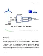
Страница 14: ...c wiring To ensure safety and easy maintenance please install the switch and fuse according to the diagram Check for output voltage consistency of the generator battery and input of inverter A mistake...

Страница 15: ...necessary to keep the system operating efficiently Using heavy grease coat the tail connection furling rod Failed furling can cause your generator to overheat and cause permanent damage Also grease t...

Страница 16: ...ion load and the charge controller The charge controller has voltage and current indicators So if there is not enough power generated the system will not output energy Also check the battery voltage s...

Страница 17: ...steps of the installation to lay down the generator Can I increase the battery capacity to increase the running time for electrical appliances o Increasing the battery capacity may cause the batterie...

Страница 18: ...egative 7 Smaller gauge wires should not be used with higher current equipment 8 Ensure that all component connections are tight and secure 9 DO NOT TOUCH any bare parts on the controller The high vol...

Страница 19: ...oating Charge Voltage 56V Control Mode charge under limited current and voltage with PWM mode Display Mode LCD Displayed Parameter Battery Voltage Charge Current Protection Type Pole confusion protect...

Отзывы:

Похожие инструкции для PowerMax+ 2000GT