background image

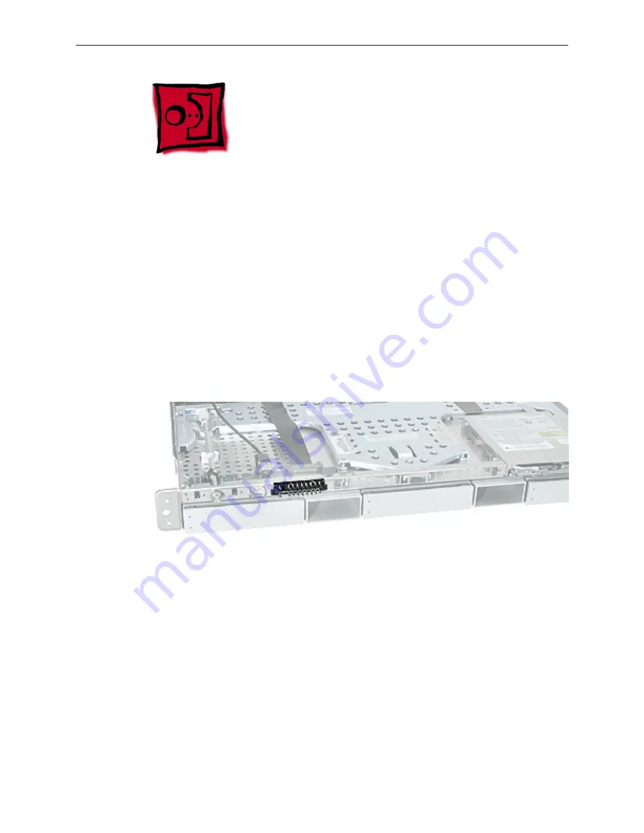
Xserve (Late 2006) Take Apart — Light Pipe for Xserve (Late 2006) 

66

Light Pipe for Xserve (Late 

2006)

Note:

 Although the illustrations for this procedure are based on Xserve G5, the procedure is the 

same for Xserve (Late 2006).

Tools

The only tool required for this procedure is a Phillips screwdriver.

Preliminary Steps

Before you begin, open the Xserve; place the bottom housing on a sturdy, flat surface; and 
remove the front bezel assembly.

Part Location

Содержание Xserve

Страница 1: ...Service Source 2006 2007 2008 Apple Inc All rights reserved Xserve Late 2006 Xserve Late 2006 Xserve Early 2008 Updated 23 December 2008...

Страница 2: ...ten consent of Apple Every effort has been made to ensure that the information in this document is accurate Apple is not responsible for printing or clerical errors Apple 1 Infinite Loop Cupertino CA...

Страница 3: ...Cards 26 PCI X and PCI E Expansion Cards 28 Battery in Xserve Late 2006 32 Battery in Xserve Early 2008 34 Optical Drive 36 Airflow Duct 39 Fan Array 42 Front Panel Board Cable 45 Backplane to Logic...

Страница 4: ...rocedure 109 Packing the Used Logic Board Xserve Early 2008 Only 113 Replacement Procedure 115 Rear ID Button 117 ID Tab 119 Enclosure 122 Troubleshooting General Information 125 What s New 125 Select...

Страница 5: ...e 145 USB Devices 146 FireWire Devices 147 Network Problems 148 Views Internal Views 150 Exploded View 1 Xserve Late 2006 150 Exploded View 2 Xserve Late 2006 151 Exploded View 1 Xserve Early 2008 152...

Страница 6: ...Service Source 2006 2007 2008 Apple Inc All rights reserved Take Apart Xserve Late 2006...

Страница 7: ...s Optical Drive Cable Added cable replacement images and steps Front Bezel for Xserve Early 2008 Added all new procedure Front Bezel Brackets Added all new procedure Light Pipe for Xserve Early 2008 A...

Страница 8: ...fore replacing or installing all parts except hard drives You can replace hard drives while the Xserve is operating and still in the rack The only noticeable external difference between the Xserve Lat...

Страница 9: ...nting in a Rack For information on mounting Xserve Late 2006 in a rack see the Xserve Late 2006 Setup Guide Tools You will need the following tools Phillips 2 scewdriver Phillips 1 screwdriver Small f...

Страница 10: ...nt Panel in the Troubleshooting chapter Note A duplicate identifier light button is on the Xserve s back panel A Note on the Images The photos and drawings in this manual were based on a pre productio...

Страница 11: ...ompatibility Xserve G4 Xserve RAID Xserve G5 Xserve Late 2006 Xserve Early 2008 PATA ADM for Xserve G4 OK OK NO NO NO SATA ADM for Xserve G5 NO NO OK OK but not supported OK but not supported SATA ADM...

Страница 12: ...You can replace or install hard drives while the Xserve is running you do not need to shut down or open the Xserve first Note There are two LED indicators on the front of each drive Drive module acti...

Страница 13: ...ommand line tools or by dragging the volume icon to the 2 Trash Press the handle on the front of the drive module so that the handle pops out Wait for the 3 upper LED on the drive to go out Then grasp...

Страница 14: ...e the language 1 From the menu bar choose Utilities Disc Utility 2 To format the primary drive use the Disc Utility on the Install disc 3 Click the Partition tab 4 Click on Options and verify GUID is...

Страница 15: ...he server from the rack If the Xserve has two power supplies they are hot swappable the Xserve will continue to operate using only one supply while the second is removed Tools No tools are required fo...

Страница 16: ...power supply slide it all the way into the 1 bay and then press the handle to seat the power supply and lock it in place Slide the power supply in and press the handle to seat it Connect the power cor...

Страница 17: ...ther bay is covered by a removable door Called a power supply blank this door keeps the empty bay clean The power supply blank may be removed while the server is still in the rack Tools No tools are r...

Страница 18: ...Xserve Late 2006 Take Apart Power Supply 18 Procedure Pull out the handle to swing open the power supply blank 1 Notice the hook that catches on the inside bottom of the power supply bay 2...

Страница 19: ...ply blank as far as it will go and then pull out the power supply blank 3 Replacement Note Align the hook on the power supply blank with the catch inside the power supply bay Close the power supply bl...

Страница 20: ...fore the top cover can be removed to gain access to any internal components Tools No tools are required for this procedure You may however find a Phillips screwdriver useful in releasing the thumbscre...

Страница 21: ...ing or installing all parts except the hard drives and power supplies Before shutting down be sure to alert users that the Xserve will be unavailable for a period of time Warning Always shut down the...

Страница 22: ...umbscrews at the back of the top cover and slide the cover back and up to 7 remove it If you have difficulty removing the cover check the enclosure lock on the front panel Important To minimize the po...

Страница 23: ...um Error correcting code ECC Important Apple recommends that you use Apple approved FB DIMMS Other FB DIMMs might degrade the performance of the Xserve DIMMs from older Xserve systems are not compatib...

Страница 24: ...se two slots Add the next pair in these two slots For Best Performance For the best performance use identical DIMMs in all slots and fill up slots 1 through 4 before you install DIMMs in slots 5 throu...

Страница 25: ...ch Ejectors Warning When removing or installing the DIMM handle it only by the edges Do not touch its connectors Lift the DIMM straight up from the connector to remove it and insert it straight down i...

Страница 26: ...riser can go in slot 1 and accepts only PCI X cards Connector on PCI X riser Connector on PCI E riser Tools The only tool required for this procedure is a Phillips 1 screwdriver Preliminary Steps Bef...

Страница 27: ...ng a blank riser card so that you can install a graphics card in the riser do the following Remove the screw on the riser bracket and remove the port access cover Seat the PCI card in the riser slot a...

Страница 28: ...um length 25 Watt maximum power consumption Slot 2 Accepts PCI Express x8 cards using a PCI E riser 6 6 inch maximum length 25 Watt maximum power consumption To install a card you first insert it into...

Страница 29: ...ocedure Loosen the two captive screws that secure the riser bracket to the back panel 1 Carefully pull up on the bracket and riser with the expansion card still attached to 2 disconnect the riser from...

Страница 30: ...not touch its connectors or any of the components on the card Lift the card straight out from the connector to remove it and insert it straight into the connector to install it Do not rock the card f...

Страница 31: ...e card 2 Tighten the captive screws that secure the riser bracket to the back panel 3 Return the Xserve to the rack and start it up 4 Configure the card 5 To configure an Ethernet card open the Networ...

Страница 32: ...em is not connected to power If the date and time change unexpectedly or other system settings are lost you might need to replace the battery Tools No tools are required for this procedure You may how...

Страница 33: ...lease the battery Warning To avoid risk of explosion replace battery only with type CR2032 Insert the new battery in the holder with the positive side facing the power supply and 3 the negative side f...

Страница 34: ...when the system is not connected to power If the date and time change unexpectedly or other system settings are lost you might need to replace the battery Tools No tools are required for this procedur...

Страница 35: ...en the spring and the holder Then slide out the battery Warning To avoid risk of explosion replace battery only with type CR2032 Insert the replacement battery in the holder with the positive side up...

Страница 36: ...procedure are based on Xserve G5 the procedure is the same for Xserve Late 2006 and Xserve Early 2008 Tools The only tool required for this procedure is a jeweler s Phillips 0 screwdriver Preliminary...

Страница 37: ...ockwise to release it 2 Placing your thumbs on the tab on either side of the drive carefully slide the drive back from 3 the front bezel Important When removing or replacing the optical drive be caref...

Страница 38: ...kets and the screws from the original drive to the replacement drive Remove the mounting screw for the left bracket and transfer the bracket to the new drive 5 using the same screw to secure it Remove...

Страница 39: ...t Airflow Duct 39 Airflow Duct Tools The only tool required for this procedure is a Phillips 1 screwdriver Preliminary Steps Before you begin open the Xserve and place the bottom housing on a sturdy f...

Страница 40: ...ither side of the airflow duct and lift it straight up and out of the Xserve 2 Caution Try not to completely remove the screws from the airflow duct Tiny black rubber washers hold these screws captive...

Страница 41: ...el under the left side of the duct Ensure the airflow duct fits flush all over and does not protrude above the level of the enclosure Be careful when working with any black foam pieces that are part o...

Страница 42: ...d for this procedure You may however find a Phillips screwdriver useful in releasing the thumbscrews in step 1 below Preliminary Steps Before you begin do the following Open the Xserve and place the b...

Страница 43: ...the fan array to remove it from the Xserve 2 Note You may need to move the front panel cable slightly out of the way of the fan array power connector during removal or replacement Be careful not to pi...

Страница 44: ...om the power connector during removal carefully rotate the fan 3 array as shown to disconnect it from the power distribution board Then lift the fan array out of the computer Replacement Note When ins...

Страница 45: ...ble Tools No tools are required for this procedure Preliminary Steps Before you begin do the following Open the Xserve and place the bottom housing on a sturdy flat surface Remove the airflow duct Rem...

Страница 46: ...Apart Front Panel Board Cable 46 Procedure Release the locking levers on the cable connectors and disconnect the front panel board 1 cable from the front panel board and the logic board Remove the ca...

Страница 47: ...O Cable 47 Backplane to Logic Board I O Cable Tools No tools are required for this procedure Preliminary Steps Before you begin do the following Open the Xserve and place the bottom housing on a stur...

Страница 48: ...ane to Logic Board I O Cable 48 Procedure Disconnect the backplane to logic board cable from the logic board 1 Disconnect the backplane to logic board cable from the drive interconnect backplane and 2...

Страница 49: ...alling the cable fold it to a 90 degree angle along its creases Replacement Note Connect the cable to the logic board first Then press the adhesive section of the cable onto the enclosure before conne...

Страница 50: ...0 Optical Drive Cable Tools No tools are required for this procedure Preliminary Steps Before you begin do the following Open the Xserve and place the bottom housing on a sturdy flat surface Remove th...

Страница 51: ...on the underside of the cable Disconnect the optical drive cable from the optical drive 1 Disconnect the optical drive cable from the logic board 2 Carefully pry the cable s adhesive from the enclosur...

Страница 52: ...al Drive Cable 52 Replacement Note Connect the replacement optical drive cable to the logic board first Then press the adhesive section of the cable onto the enclosure before connecting the other end...

Страница 53: ...the illustrations for this procedure are based on Xserve G5 the procedure is the same for Xserve Late 2006 and Xserver Early 2008 Tools No tools are required for this procedure Preliminary Steps Befo...

Страница 54: ...the rod and remove the rod from the server 2 If you are replacing the plastic gear on the end of the rod slide the gear off the rod 3 Replacement Procedure To install the gear slide it onto the notch...

Страница 55: ...hanism Rod 55 To install the locking rod insert the key hole end of the rod into the port on the front bezel 2 Note Make sure the small circle on the front of the rod points to the left It should alig...

Страница 56: ...Note Although the illustrations for this procedure are based on Xserve G5 the procedure is the same for Xserve Late 2006 Tools The only tool required for this procedure is a Phillips screwdriver Prel...

Страница 57: ...ach the two front bezel brackets to 1 the server and remove the brackets Remove the screw that attaches the top of the bezel to the server 2 Gently pull the front bezel forward and remove it from the...

Страница 58: ...nal front bezel to the 1 replacement bezel Position the light pipes in the light pipe assembly into the double row of light pipe holes in 2 the front bezel Replace the front bezel on the server matchi...

Страница 59: ...ewdriver Preliminary Steps Before you begin open the Xserve and place the bottom housing on a sturdy flat surface Part Location Removal Procedure From behind the front bezel locate the four screws and...

Страница 60: ...replacing the bezel be careful not to put pressure on the top of the bezel over the optical drive slot Replacement Procedure Leave the power button and system identifier button on the server but note...

Страница 61: ...ure in the front bezel If it comes out align the pins to the 2 front bezel and insert it into the slot in the front bezel Place the front bezel on the server carefully matching openings with buttons a...

Страница 62: ...erve Early 2008 62 Front Bezel Brackets for Xserve Early 2008 Tools The only tool required for this procedure is a Phillips screwdriver Preliminary Steps Before you begin open the Xserve and place the...

Страница 63: ...ntical 4 mm long screws and the two brackets Important When removing or replacing the bezel brackets be careful not to put pressure on the top of the bezel over the optical drive slot Replacement Proc...

Страница 64: ...ins how to remove the power and system ID buttons from the front bezel Tools The only tool required for this procedure is a Phillips screwdriver Preliminary Steps Before you begin open the Xserve plac...

Страница 65: ...lift straight up and remove the button from the 1 front bezel Repeat for the system ID button 2 Note Take care in handling the buttons The face of each button is loosely attached to the button LEDs an...

Страница 66: ...ations for this procedure are based on Xserve G5 the procedure is the same for Xserve Late 2006 Tools The only tool required for this procedure is a Phillips screwdriver Preliminary Steps Before you b...

Страница 67: ...nd then the other side of the light pipe assembly from its opening in the 1 front of the enclosure Remove the light pipe assembly from the server 2 Replacement Procedure Position the light pipes in th...

Страница 68: ...ipe for Xserve Late 2006 68 Replace the front bezel on the server matching ports projections with openings 2 Replace the screw that secures the top of the bezel to the server 3 Replace the two bezel b...

Страница 69: ...69 Light Pipe for Xserve Early 2008 Tools The only tool required for this procedure is a Phillips screwdriver Preliminary Steps Before you begin open the Xserve place the bottom housing on a sturdy fl...

Страница 70: ...rocedure Align the pins on the replacement light pipe assembly with the pin openings in the front 1 bezel Gently press the light pipe assembly onto the front bezel 2 Replace the front bezel on the ser...

Страница 71: ...anel Board Tools The only tool required for this procedure is a Phillips 1 screwdriver Preliminary Steps Before you begin do the following Open the Xserve and place the bottom housing on a sturdy flat...

Страница 72: ...Panel Board 72 Procedure Release the two locking levers on the front panel board cable connector and disconnect the 1 cable from the front panel board Remove the two Phillips screws that mount the fr...

Страница 73: ...lide the board back slightly and release the two clips on either side of it 3 Tilt the board up and remove it from the Xserve 4 Important When replacing the front panel board make sure the board slide...

Страница 74: ...e You may however find a Phillips screwdriver useful in releasing the thumbscrew Preliminary Steps Before you begin do the following Open the Xserve and place the bottom housing on a sturdy flat surfa...

Страница 75: ...e connector and disconnect the 1 cable from the front panel board Move the front panel board cable out of the way Disconnect the backplane to logic board I O cable from the backplane 2 Replacement Not...

Страница 76: ...haped standoffs that hold the backplane in place Rotate the backplane up slightly from the logic board side as shown and carefully pull the 5 backplane up and toward the logic board to free it from th...

Страница 77: ...nt edge of the backplane with the four backplane alignment slots in the enclosure Be careful not to let any backplane components come into contact with the standoffs or the enclosure as you install th...

Страница 78: ...hillips screwdriver useful in releasing the thumbscrew Preliminary Steps Before you begin do the following Open the Xserve and place the bottom housing on a sturdy flat surface Remove all Apple drive...

Страница 79: ...the front panel board cable connector and disconnect the 1 cable from the front panel board Move the front panel board cable out of the way Disconnect the backplane to logic board I O cable from the X...

Страница 80: ...ion of the arrow shown 5 until it clears the four mushroom shaped standoffs that hold the card in place Rotate the Xserve RAID Card up slightly from the logic board side as shown and carefully 6 pull...

Страница 81: ...not to let any Xserve RAID Card components come into contact with the standoffs or the enclosure as you install the card Then rotate the Xserve RAID Card downward and over the four mushroom shaped sta...

Страница 82: ...ble 82 Power Distribution Board Cable Tools The only tool required for this procedure is a nylon probe tool or similar plastic pry tool Preliminary Steps Before you begin open the Xserve and place the...

Страница 83: ...imilar plastic pry tool to gently yet firmly pry outwards on the cable connector while depressing the cable connector latch with your thumb and forefinger to separate the connectors Disconnect the pow...

Страница 84: ...ary Steps Before you begin do the following Open the Xserve and place the bottom housing on a sturdy flat surface Remove all Apple drive modules Remove both power supplies Remove the airflow duct Remo...

Страница 85: ...ing posts 1 Note Adhesive on the underside of the battery holds it in place on the enclosure floor Remove the battery from the enclosure 2 Replacement Note Before installing a new battery remove the p...

Страница 86: ...crush incinerate or expose the battery to temperatures above 212 F 100 C Stop using the battery if it appears damaged in any way Replace the battery only with an Apple authorized battery for this pro...

Страница 87: ...wdriver useful in releasing the thumbscrew Preliminary Steps Before you begin do the following Open the Xserve and place the bottom housing on a sturdy flat surface Remove all Apple drive modules Remo...

Страница 88: ...at secures the power distribution board to the enclosure 1 Note The thumbscrew is captive you cannot remove it Pull the board toward the side of the enclosure in the direction shown to disconnect it f...

Страница 89: ...hermal grease New grease and alcohol wipes for cleaning off the previous grease are included with replacement heat sinks processors logic boards ID tabs and enclosures Grease and wipes are also availa...

Страница 90: ...0 Part Location Procedure Note Server configurations with a single processor have a regular heat sink and a blank heat sink installed The blank heat sink is silver colored as shown below and should no...

Страница 91: ...Xserve Late 2006 Take Apart Processor Heat Sink 91 Loosen the four screws securing the heat sink that is closest to the DIMM slots CPU A in the 1 order indicated below...

Страница 92: ...ake Apart Processor Heat Sink 92 Caution Whenever you handle the heat sink handle it from the slotted sides not the smooth sides Grasping the smooth sides of the heat sink can compress its ribs causin...

Страница 93: ...heat sink be especially cautious to initially lift the heat sink no more than one centimeter 1 cm offthe processor Do not pull on the cable as you lift the heat sink enough to disconnect the cable fr...

Страница 94: ...are included with the replacement heat sink Clean the processor and apply new grease as follows Release the latch on the metal processor holder for the processor 1 Rotate the top of the holder to the...

Страница 95: ...ith the replacement part being careful not to get any thermal grease on the processor contacts Apply the entire contents on a single syringe of thermal grease approximately 4 5 cc to the 5 top surface...

Страница 96: ...venly over the entire top surface of the processor Scrape off any excess grease with the package edge then discard the package Holding the processor by three corners only keep the processor level as y...

Страница 97: ...Then lower the processor straight down onto the socket Rotate the top of the holder to the closed position 8 Engage the latch on the metal processor holder 9 Holding the heat sink in one hand reconne...

Страница 98: ...s in the 11 logic board Tighten the four captive Phillips mounting screws for the heat sink in the order indicated 12 below Do not over tighten the screws If you have a torque driver tighten the screw...

Страница 99: ...nd alcohol wipes for cleaning off the previous grease are included with replacement processors and logic boards Instructions for applying the grease are included with the heat sink removal procedure N...

Страница 100: ...Xserve Late 2006 Take Apart Processor 100 Part Location Removal Procedure Release the latch on the metal processor holder 1 Rotate the top of the holder to the open position 2...

Страница 101: ...removing or installing a processor always hold the processor by three corners Be extremely careful not to touch the gold pins on the bottom of the processor as this type of connector is very sensitiv...

Страница 102: ...with the replacement processor apply the 1 entire contents of the syringe approximately 4 5 cc to the top surface of the processor Important Be sure not to get grease anywhere on the processor other...

Страница 103: ...sor 103 Holding the processor by three corners only keep the processor level as you place it into its 3 holder on the logic board being careful not to get any thermal grease on the contacts of either...

Страница 104: ...ogic board align the processor notch with the tab on the processor holder as shown Then lower the processor straight down onto the socket Rotate the top of the holder to the closed position 4 Engage t...

Страница 105: ...he only tool required for this procedure is a Phillips 1 screwdriver Preliminary Steps Before you begin do the following Open the Xserve and place the bottom housing on a sturdy flat surface Remove th...

Страница 106: ...n all sides of the card to disconnect it from its logic board connector under 2 the card and remove the card from the Xserve Replacement Note When installing the mezzanine card be sure to press down g...

Страница 107: ...an array Backplane to logic board I O cable Both processor heat sinks Both processors remove only if you are installing a replacement logic board Video mezzanine card remove only if you are installing...

Страница 108: ...2006 Take Apart Logic Board 108 Part Location Caution Although the logic boards for Xserve Late 2006 and Xserve Early 2008 are a similar size do not install an older logic board in the Xserve Early 2...

Страница 109: ...ore continuing with the 1 steps Caution When removing and installing the logic board be careful not to flex the logic board which could damage the board or its components To best distribute the weight...

Страница 110: ...hen transferring the logic board be careful not to flex the logic board which could damage the board or its components To best distribute the weight of the logic board and minimize flexing hold the lo...

Страница 111: ...d disconnect the 3 cable from the logic board Move the cable aside so you have access to the logic board Loosen the single thumbscrew on the power distribution board and slide the board away 4 from an...

Страница 112: ...d to the 5 enclosure Use the same order when replacing the logic board Note The thumbscrews are captive you cannot remove them Grasping the logic board only by its expansion card riser and edge as sho...

Страница 113: ...s When packing the logic board place the board in an antistatic bag and set it component side up in the return box so that the raised areas on the board fit correctly between the foam supports on the...

Страница 114: ...ponent side up and positioned with 3 the Northbridge heat sink at the back of the box Follow any additional return instructions for your region and close the box 4 Important Make sure the foam support...

Страница 115: ...d raised 1 2 inches 3 5 cm guide the connectors on the back edge of the board into the openings in the back panel of the chassis then lower the front edge of the board into place Take special care to...

Страница 116: ...he logic board in the Xserve changes its Ethernet ID numbers MAC addresses for both Ethernet ports The new numbers are printed on an Ethernet label packaged with the replacement logic board After inst...

Страница 117: ...only tool required for this procedure is needlenose pliers Preliminary Steps Before you begin do the following Open the Xserve and place the bottom housing on a sturdy flat surface Remove the right PC...

Страница 118: ...of the Xserve to carefully disengage the button s additional two prongs from the logic board Continue to pull up and toward the front of the Xserve to disengage the button from the 3 opening in the re...

Страница 119: ...eplacement ID tab The grease and wipes are also available through a separate thermal grease kit on GSX order part number 076 1237 which contains enough grease for both processors Tools No tools are re...

Страница 120: ...e Apart ID Tab 120 Part Location Procedure Once the logic board has been removed from the enclosure the ID tab will be visible on the 1 inside bottom of the enclosure the tab protrudes from the rear p...

Страница 121: ...e 2006 Take Apart ID Tab 121 Gently grasp the ID tab and pull up on it to disengage it from the channel that it slides along 2 in the enclosure Pull the ID tab through the slot in the rear panel to re...

Страница 122: ...order part number 076 1237 which contains enough grease for both processors Tools No tools are required for this procedure Preliminary Steps Before you begin open the Xserve place the bottom housing o...

Страница 123: ...Xserve Late 2006 Take Apart Enclosure 123 Part Location Procedure Once all other components have been removed from the enclosure what is left is the enclosure itself...

Страница 124: ...Service Source 2006 2007 2008 Apple Inc All rights reserved Troubleshooting Xserve Late 2006...

Страница 125: ...DIMM 240 pin 2 GB 2x1GB Graphics Card ATI Radeon X1300 RV515 ATI Radeon X1300 RV516 Hard Drive configurations 80 GB Serial ATA 300 7200 rpm 73 GB 300 GB 750 GB 80 GB Serial ATA 300 7200 rpm 73 GB 300...

Страница 126: ...perating system installed on it You can replace or install hard drives while the Xserve is running you do not need to shut down or open the Xserve first but you may need to dismount the drive from the...

Страница 127: ...er Xserve systems are not compatible with this Xserve Note Before you purchase DIMMs other than those recommended by Apple make sure that the memory manufacturer conforms to the Joint Electronic Devic...

Страница 128: ...s in slots 5 through 8 If you don t have eight identical DIMMs install identical DIMMs in slots 1 through 4 and a second set of four identical DIMMs in slots 5 through 8 If you can after you fill slot...

Страница 129: ...serve has two power supplies and no AC power is available to one of the power supplies or if one of the power supplies has failed that power supply s status LED will illuminate SOLID RED Note In a red...

Страница 130: ...PCI X cards Slot 2 which accepts half length 6 6 inch PCI E cards Expansion slot 1 PCI E or PCI X Expansion slot 2 PCI E The Xserve Late 2006 accepts PCI cards that meet these specifications Slot 1 Ac...

Страница 131: ...from any other available system Start up in target disk mode Reset NVRAM and start up from first bootable drive module Not used Start up in diagnostic mode from a NetBoot server When you have made you...

Страница 132: ...scape 1 Restart Control Command Power 2 Force Shut Down press the power button for 10 seconds 3 Resetting the SMC can resolve some Xserve issues such as not starting up not displaying video sleep issu...

Страница 133: ...may need to be replaced Power On Self Test POST Error Indications A power on self test in the Xserve s ROM automatically runs whenever the Xserve is started up after being fully shut down the test do...

Страница 134: ...erve System status LEDs 1 in the illustration below CPU status LEDs 2 in the illustration below EFI POST LEDs 3 in the illustration below The LEDs are located toward the rear of the logic board You mu...

Страница 135: ...or replace PCI expansion cards or FB DIMMs because the Xserve is still powered on DS9C4 5VSTBY If the DS9C4 LED is OFF do the following Check that the AC cord is connected to a working AC wall outlet...

Страница 136: ...fy the airflow duct is properly in place and nothing is blocking its airflow DS9C7 CPUB_HLTH and DS9C8 CPUB_HLTH If DS9C7 or DS9C8 LED is ON do the following With the Xserve booted press the SYS_RST s...

Страница 137: ...ash briefly when the computer is started up or shut down and when it goes in and out of sleep mode This is normal behavior Troubleshooting Shutdown and restart the computer Try reseating the FB DIMMs...

Страница 138: ...in AC power cord and press the power on button on the front panel LED DSC9C6 should be ON when the Xserve starts up indicating that the main power is OK and within regulation If you cannot verify thes...

Страница 139: ...port is replaced by a USB port as shown below On standby button and light On standby button and light Press to turn on the Xserve Press for 10 seconds to force the Xserve to shut down if all other sh...

Страница 140: ...port 2 System activity lights Four groups of four lights indicate system activity The front panel system activity LEDs will flash blue intermittently to represent an estimate of processor activity an...

Страница 141: ...rieve logs of activity and Apple System Profiler reports on remote Xserves Restart and shut down a remote Xserve Alert you via email and or page when a significant service issue arises Apple Xserve Di...

Страница 142: ...nd power LED is not illuminated Verify that the rear system ID button on the back of the logic board aligns with the opening 1 in the chassis back panel If it does not realign the logic board Verify t...

Страница 143: ...ning the power LED is illuminated but there are no activity lights or video on external display Verify that the rear system ID button on the back of the logic board aligns with the opening 1 in the ch...

Страница 144: ...oard 11 System shuts down almost immediately after startup Reset the SMC Refer to Resetting the SMC in this chapter 1 Replace both processors 2 Replace the power supply 3 Replace the logic board 4 Bui...

Страница 145: ...mage to its connector 2 or the connector in that drive bay of the Xserve Do not re install the drive module if its connector is damaged or if the drive bay connector in the Xserve is damaged If there...

Страница 146: ...he trash or select it and press Command E 3 Connect a USB mouse and restart the Xserve while holding down the mouse button to 4 attempt to eject the disc Verify that the bezel over the slot is not ben...

Страница 147: ...re device connected to port on back panel No FireWire device icon appears on the desktop If the Xserve is locked unlock it 1 Verify that the FireWire device is turned on and the FireWire cable is secu...

Страница 148: ...t panel board 8 Network Problems Server cannot be seen on network Open the Network system preference pane and select the built in Ethernet option Verify 1 that you can now see devices on the network I...

Страница 149: ...Service Source 2006 2007 2008 Apple Inc All rights reserved Views Xserve Late 2006...

Страница 150: ...Expansion Cards 661 4047 661 4048 661 4197 661 4206 661 4194 661 4195 Video Mezzanine Card 661 4205 Riser Card PCI X 922 7860 PCI E 922 7861 FB DIMMs 512 MB 661 4189 1 GB 661 4190 2 GB 661 4191 4 GB 6...

Страница 151: ...e Combo 661 4033 Super 661 4034 Hard Drive 80 GB 661 4029 73 GB 661 4031 300 GB 661 4032 750 GB 661 4100 Logic Board 661 4187 Light Pipe Kit 076 0984 Front Bezel 922 6354 Locking Rod 922 6328 Power Su...

Страница 152: ...d Cable 922 8475 Expansion Cards 661 4197 661 4195 Video Mezzanine Card 661 4655 Riser Card PCI X 922 8454 PCIE 8X 922 8452 PCIE 16X 922 8453 FB DIMMs 1 GB 661 4645 2 GB 661 4646 4 GB 661 4647 Power D...

Страница 153: ...2 8545 Optical Drive Super 661 4477 Hard Drive 80 GB 661 4473 73 GB 661 4474 300 GB 661 4476 1 TB 661 4475 Logic Board 661 4631 Light Pipe Kit 076 1287 Front Bezel 922 8476 Locking Rod 922 8478 Power...

Страница 154: ...ht Enclosure lock and status light FireWire 400 port On standby button and light Drive Module bays 3 Ethernet link light Port 1 Ethernet link light Port 2 System activity lights Note The front bezel o...

Страница 155: ...800 ports 2 Ethernet port 2 Ethernet port 1 Expansion slot 1 Expansion slot 2 Display port Serial console port USB 2 0 ports 2 Note The rear panel of the Xserve Early 2008 and Xserve Late 2006 model...

Страница 156: ...Service Source 2006 2007 Apple Inc All rights reserved Appendix Xserve Late 2006...

Страница 157: ...Xserve Late 2006 Reference for Internal Sensors 157 Reference for Internal Sensors...

Страница 158: ...Xserve Late 2006 Reference for Internal Sensors 158...

Страница 159: ...Xserve Late 2006 Reference for Internal Sensors 159...

Страница 160: ...Xserve Late 2006 Reference for Internal Sensors 160...

Страница 161: ...Xserve Late 2006 Reference for Internal Sensors 161...

Страница 162: ...Xserve Late 2006 Reference for Internal Sensors 162...

Страница 163: ...Xserve Late 2006 Reference for Internal Sensors 163...

Страница 164: ...Xserve Late 2006 Reference for Internal Sensors 164...

Страница 165: ...Xserve Late 2006 Reference for Internal Sensors 165...

Отзывы: