- if everything mentioned above fails, try to update the sensor’s FW
- if the update fails too, take a multimeter and measure the sensor’s power
consumption and the voltage readings on the orange and white wires of
the sensor, make a short video of that check and send it to us;
To check the power consumption of the sensor, select the A
⎓
option on
your multimeter/multitester. One of the probes of the multimeter must be
connected to the
COM socket
and the other – to the
mA socket
.
Then the sensor’s black wire must be connected to the GND of the power
supply. One probe of the multimeter has to be connected to the red wire of the
sensor and the other one to the PWR wire of the power supply.
Fig. 58 Power consumption (amperage) check
Compare the reading you get with the normal values indicated in the table
below. Take a photo or record a short video of the check.
To check if the line A and line B of the sensor are intact, connect one of the
multimeter’s probe (the one plugged into the multimeter’s COM socket)
between the black wire of the sensor and the GNR of the power supply. The
other probe (the one plugged into the multimeter’s V
⎓
socket) must be
47
Содержание TD-150
Страница 6: ...6...
Страница 15: ...Fig 13 Additional files Fig 14 Windows components and libraries Fig 15 RuntimePack is installed 15...
Страница 50: ...Fig 61 2 Setting Full and Empty values manually Fig 61 3 Setting Full and Empty values manually 50...
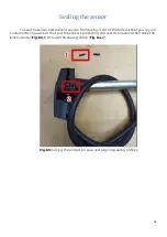
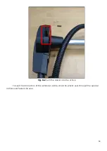
Страница 54: ...Fig 65 Sealing cable connection point Fig 66 Sealing sensor old design 54...


