


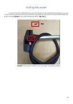


connected first to the line A (orange wire of the sensor) and then to the line B
(white wire of the sensor). Power the sensor up.
Fig. 59 Line A voltage check (relative to GND)
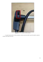
Fig. 60 Line B voltage check (relative to GND)
Compare the readings you get on both A and B lines with the normal
values indicated in the table below.
Table 3
48
Содержание TD-150
Страница 6: ...6...
Страница 15: ...Fig 13 Additional files Fig 14 Windows components and libraries Fig 15 RuntimePack is installed 15...
Страница 50: ...Fig 61 2 Setting Full and Empty values manually Fig 61 3 Setting Full and Empty values manually 50...
Страница 54: ...Fig 65 Sealing cable connection point Fig 66 Sealing sensor old design 54...