


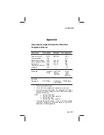

Appendix
Appendix 2
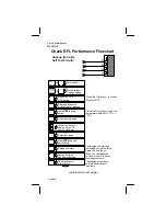
Notes on AC line Analysis Procedures
Loop current and circuit loss work together. When loop
current approaches –23 mA the circuit loss should be
approximately –8.0 dBm. If the loop current is low and the
circuit loss is less than –8.0 dBm, the problem is probably a
defective loop aid. If the loop current is good and the circuit
loss is high, the problem is either bridged tap or incorrect
loading. If both loop current and circuit loss are bad, the
problem is incorrect resistance zoning. When circuit loss
exceeds –8.5 dBm, the actual measured loss should be
compared with an estimated measured loss based on loop
make–up. If they differ significantly, dial up a step tone
generator and make a frequency run to check loading. If both
actual and estimated loss exceed –8.5 dBm and are
approximately the same, install a VF repeater to decrease the
loss.
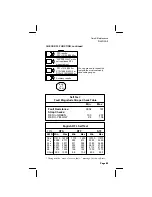
Noise and Power influence work together. If noise is high
and power influence is low, the problem most likely is a
defective pair. If power influence is high, the problem is an
open shield or missing ground.
For touch dialing problems, dial up a step tone generator
and make a frequency run to check for loaded bridge tap.
If in doubt, measure additional pairs. If other pairs are
good, your problem is a single bad pair. If other pairs read
defective as the one you’re working on, the problem is in the
cable or complement.
For 2–party lines, a missing ringer isolator at one party
causes noise to the other party. Ringer isolators must be
placed at both parties.
Unacceptable Balance When noise and power influence are
shown as acceptable, but the balance reading is not, such as:
Noise = 19.3 dBrnC (OK)
Power Influence = 68.2 dBrnC (OK)
Balance = 48.9 dBrnC (unacceptable)
The unacceptable balance reading is a clue that there may be
noise problems during peak power periods when power


