background image


62 


Step 7)


Repeat step 1 until 4 until all blades are placed.  

Step 8)


The hexagon shaped part of the shaft should be completely 

covered with shredder blades and spacers. In the illustration below, the blade 
and spacer have an 1,3mm overlap. The overlap may vary as long as there is 
some overlap. 


Содержание GP20 Hybrid

Страница 1: ...GP20 Hybrid Version 2 0 October 2023 English user guide...

Страница 2: ...COMPANY INFO 3devo B V Atoomweg 478 3542 AB Utrecht The Netherlands www 3devo com support 3devo com...

Страница 3: ...ES 14 2 2 3 GP20 GRANULATOR ACCESSORIES 14 2 2 4 GP20 HYBRID ACCESSORIES 15 2 2 5 OPTIONAL ACCESSORIES 15 2 3 TECHNICAL SPECIFICATIONS 16 3 INSTRUCTIONS 17 3 1 QUICK USER GUIDE 17 3 2 INSTALLATION INS...

Страница 4: ...51 3 5 2 GP20 SHREDDER CUTTING CHAMBER 52 3 5 2 1 REMOVING AND INSTALLING SCRAPER COMBS 53 3 5 2 2 REMOVING AND INSTALLING SHREDDER BLADES 56 3 5 3 GP20 GRANULATOR CUTTING CHAMBER 65 3 5 3 1 OPEN GRAN...

Страница 5: ...low reaction response time physical or intellectual impairments The manufacturer is not liable for any damage or other problems caused by the user s failure to observe these instructions WARNING Ear...

Страница 6: ...nts of the machine this can cause extremely dangerous situations WARNING Only use the GP20 Hybrid with the 3devo hopper mounted on the machine WARNING Never change or remove guards when the machine is...

Страница 7: ...use the machine blades to wear out fast Non plastic materials can also damage the machine itself Always make sure the plastic parts do not contain any non plastic pieces or particles CAUTION Check if...

Страница 8: ...4 2 OVERVIEW 2 1 GP20 HYBRID OVERVIEW 1 Hopper 2 GP20 Shredder 3 GP20 Granulator 4 Trolley 5 Container...

Страница 9: ...from escaping the machine The Hopper uses a flat belt drive that helps feeding material to the GP20 Shredder and or GP20 Granulator 1 Hopper connector 2 Mounting slots 3 Input 4 Thumb screw for chang...

Страница 10: ...Conveyor belt 11 Thumb screw for fixing the belt cover 12 Hooks for toggle clamps 13 Safety sensor actuator Only for GP20 Granulators 14 Granule guard Read more about installing the Hopper in chapter...

Страница 11: ...x 2 Shredder blades 3 Hopper detection sensor 4 Scraper comb 5 Positioning pin for hopper 6 Bolts for fixing scraping combs 7 Positioning pin for container 8 Control box connector 9 Bolts for front co...

Страница 12: ...tainer or GP20 Granulator 13 Positioning holes for Trolley or GP20 Granulator 14 Motor 15 Bolts for front plate for removing installing shredder blades Only used for GP20 Hybrids 16 Safety sensor actu...

Страница 13: ...9 2 1 3 GP20 GRANULATOR OVERVIEW 1 Control box 2 Handlebar 3 Toggle clamp 4 Rotary knife...

Страница 14: ...ction sensor 13 Toggle clamps for hopper or GP20 Shredder for GP20 Hybrid setup 14 Bolt for removing installing the Rotor 15 Hook for Container toggle clamps 16 Positioning holes for Trolley 17 Motor...

Страница 15: ...nterface 6 Control knob 7 Hopper port 8 Safety circuit port 9 Motor cable port 10 Mounting holes only used for GP20 Shredder 11 Mounting holes only used for GP20 Granulator 12 Positing hole for Trolle...

Страница 16: ...lator 15 Machine link port Only used in GP20 Hybrid mode 2 1 5 TROLLEY OVERVIEW 1 Positioning pins for GP20 Shredder or GP20 Granulator 2 2x Wheel with brakes 3 2x Wheel without brakes 4 Wheel assembl...

Страница 17: ...IEW 1 Positioning slots for GP20 Granulator or GP20 Shredder 2 Actuator for GP20 Shredder or GP20 Granulator safety sensor 3 Toggle clamps 4 Handlebar 5 Container lid Read more about installing the Co...

Страница 18: ...llen key 8mm Allen key 2 2 2 GP20 SHREDDER ACCESSORIES 1x Power cable 1x USB cable 2x Safety circuit cable 2x Scraper combs 4x Hexagon head screws M6 x 20 4x Button head screws M6 x 20 3x M8 lock nut...

Страница 19: ...GP20 HYBRID ACCESSORIES 1x Machine link cable 3x Positioning studs 3x Hexagon head screws M8 x 14 3x M8 washer 2 2 5 OPTIONAL ACCESSORIES 2 teeth shredder blades 3 teeth shedder blades 7 teeth shredde...

Страница 20: ...220 240Vac 50 60Hz 1200 Watt Energy consumption shredder AC 220 240Vac 50 60Hz 1200 Watt Energy consumption granulator USA AC 110 120Vac 50 60Hz 1500 Watt Energy consumption shredder USA AC 110 120Vac...

Страница 21: ...first 3 1 QUICK USER GUIDE For the fast starters out there we have made a short and simple out of the box quick start guide This is shipped in your GP20 accessory box or you can download it from www...

Страница 22: ...18 Step 2 If all the Wheel assemblies are in place tighten the bolts fully...

Страница 23: ...NSTALLATION INSTRUCTIONS GP20 SHREDDER Step 1 Remove the four bolts on top of the Control box Shredder assembly Step 2 Slide the Control box Shredder away from the motor to create space around the mot...

Страница 24: ...redder compartment and secure the two items with 4x hexagon head screws M6 x 20 10mm wrench Step 4 Slide the Control box Shredder back on and attach the Control box Shredder to the motor using 4x butt...

Страница 25: ...bolts on the sides using an 8mm Allen key This will secure the Scraper combs in place More information about this can be found in chapter 3 5 2 1 Step 6 Place the Trolley on a flat and stable place on...

Страница 26: ...he three mounting holes on the bottom of the GP20 Shredder The holes should be positioned on the three threaded positioning studs on top of the Trolley Step 8 Carefully lift the GP20 Shredder with two...

Страница 27: ...23 Step 9 Secure the GP20 Shredder in place by placing M8 washers and nuts on the threaded positioning studs...

Страница 28: ...24 3 2 3 INSTALLATION INSTRUCTIONS GP20 GRANULATOR Step 1 Remove the four bolts on top of the Control box Granulator assembly...

Страница 29: ...e the Control box Granulator away from the motor to create space around the motor flange Step 3 Mount the motor on the Granulator compartment and secure the two items with 4x hexagon head screws M6 x...

Страница 30: ...back on and attach the Control box Granulator to the motor using 4x button head screws M6 x 20 4mm Allen key Step 5 Place the Trolley on a flat and stable place on the floor close to a power socket Ma...

Страница 31: ...the three mounting holes on the bottom of the GP20 Granulator The holes should be positioned on the three threaded positioning studs on top of the Trolley Step 8 Carefully lift the GP20 Granulator wi...

Страница 32: ...uts on the threaded positioning studs 3 2 4 INSTALLATION INSTRUCTIONS GP20 HYBRID Step 10 Place the Trolley on a flat and stable place on the floor close to a power socket Make sure the fuses are rate...

Страница 33: ...positioned on the three threaded positioning studs on top of the Trolley Step 13 Carefully lift the GP20 Granulator with two persons on top of the threaded positioning studs of the Trolley Step 14 Se...

Страница 34: ...tioning studs on the GP20 Granulator using three M8 x 14 hexagon bolts and three washers Step 16 Locate the three mounting holes on the bottom of the GP20 Shredder The holes will be positioned on the...

Страница 35: ...31 Step 17 Carefully lift the GP20 Shredder with two persons on top of the threaded positioning studs of the GP20 Granulator...

Страница 36: ...32 Step 18 Secure the GP20 Shredder in place by placing M8 washers and nuts on the threaded positioning studs For Hybrid mode the safety switches must be configured correctly...

Страница 37: ...he safety actuator from the GP20 Shredder down until it clicks Tighten the thumb screw Step 20 Loosen the thumb screw of the Granulator like shown below Slide the safety actuator from the GP20 Granula...

Страница 38: ...st be taken Inspect the plastic parts for any impurities such as other types of plastic non plastics or dust Remove as much as possible to prevent any damage to the machine and keep the output materia...

Страница 39: ...the following Collecting output material Removing access to danger zones of the machine Keeping the filter screen in place Only applies when placed underneath the GP20 Granulator Step 1 Place the Cont...

Страница 40: ...e U shaped brackets on the right side of the Container around the hooks of the GP20 Granulator OR GP20 Shredder and fasten the toggle clamps Before applying any power to the toggle clamps ensure that...

Страница 41: ...g pins of the GP20 Granulator OR GP20 Shredder 3 3 2 MOUNTING THE HOPPER The hopper can be easily installed and removed WARNING Turn off the power switch when the hopper cable needs to be connected or...

Страница 42: ...38 Step 1 Place the Hopper on top of the GP20 Granulator OR GP20 Shredder Step 2 Hook the mounting slots on the bottom of the Hopper to the positioning pins of the GP20 Granulator OR GP20 Shredder...

Страница 43: ...ly into its designated slot Step 4 Place the U shaped brackets of the GP20 Granulator OR GP20 Shredder around the hooks of the Hopper Before applying any power to the toggle clamps ensure that the mou...

Страница 44: ...de of the positioning pins of the GP20 Granulator OR GP20 Shredder Step 5 Insert the connector of the cable attached to the Hopper in the Control Box Shredder Removing the hopper is useful in the foll...

Страница 45: ...41 Resolving an obstruction in the hopper Machine is overloaded Gaining access to the machine during the cleaning process...

Страница 46: ...using the following tools Vacuum cleaner Pressurized air Brush Screwdriver Tweezer or similar object Step 5 Optional a to thoroughly clean cutting chamber of the shredder you can take the shredder bl...

Страница 47: ...granulator door to gain access to the cutting chamber Step 5 Remove filter screen More information about this can be found in chapter 3 5 3 2 Step 6 Optional for thorough cleaning also remove the Rot...

Страница 48: ...matches the voltage indicated on the sticker next to the power socket Step 3 Press the on switch The display will show the home screen where the status of the machine is shown as well as the temperatu...

Страница 49: ...not too big to be fed into the opening of the granulator Step 7 Press Stop Granulating in the main menu if you are finished granulating It is advised to only do this if the granulating chamber is com...

Страница 50: ...the feeding aperture depends on the size of the input material and the amount of material that can be fed at once to the machine If you only have a GP20 Granulator the hopper has an additional barrier...

Страница 51: ...47...

Страница 52: ...an be customized by for example adding flaps The belt scrapers will need to be adjusted accordingly to prevent the conveyor belt from being blocked Simply loosen the two screws of each belt scraper an...

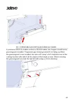
Страница 53: ...have a granule guard installed The granule guard stops granules from flying up When the granule guard is not installed the rotor will scoop all of the plastics out of the cutting chamber after which...

Страница 54: ...50 When reinstalling keep in mind to insert the tabs inside the cut outs before tightening the screws...

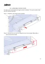
Страница 55: ...cover can be removed to gain access to the belt This can be useful when the belt requires cleaning Step 1 Untighten the thumb screws partially Step 2 Remove the cover by first sliding the cover horizo...

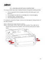
Страница 56: ...vided regarding adjustments and maintenance to the cutting chamber of the GP20 Shredder WARNING Make sure the machine is turned off and the power plug is removed before proceeding with the next steps...

Страница 57: ...machine from overloading due to material wedging Self cleaning the cutting chamber Preventing material to come back up It is advised to remove the Scraper combs prior to cleaning the cutting chamber...

Страница 58: ...54 Step 3 Carefully pull the scraper comb up and lift it out...

Страница 59: ...mbs the same steps can be done in reverse as shown above Step 1 Lower the Scraper combs inside of the machine Step 2 Tighten the bolts on the side using an 8mm Allen key This will keep the scraper com...

Страница 60: ...NG AND INSTALLING SHREDDER BLADES Step 1 Remove the scraper combs as explained in the previous chapter Step 2 Unscrew the two bolts on the front of the machine using an 8mm Allen key and remove the bl...

Страница 61: ...57 Step 3 The ends of the shredder shafts are now exposed Remove all four hexagon nuts from both shafts Step 4 Unscrew the four bolts using an 8mm Allen key and slide the front plate towards you...

Страница 62: ...58...

Страница 63: ...he shredder shafts all shredder blades and shredder spacers are cleaned properly If dust or contaminant get stuck between the blades the right clearance cannot be ensured which may result in extreme d...

Страница 64: ...e clockwise direction Step 2 Slide one shredder spacer on the right shaft opposing the shredder blade Step 3 Slide another shredder blade on the right shaft Make sure the teeth are pointing in the cou...

Страница 65: ...the shredder blade for your reference Step 6 The recommended configuration for 7 teeth blades is to stack each subsequent blade one sixth turn with respect to the previous blade of the same shaft In c...

Страница 66: ...ades are placed Step 8 The hexagon shaped part of the shaft should be completely covered with shredder blades and spacers In the illustration below the blade and spacer have an 1 3mm overlap The overl...

Страница 67: ...one thin nut per shaft and tighten the nuts a little bit at a time Even tightening is important to avoid imbalances in the stacked blades Step 11 If both thin nuts are tightened and there is no play i...

Страница 68: ...Step 12 Screw in the four bolts in the corners of the front plate using a 8mm Allen key Step 13 Mount the black casing plate back on the machine by screwing in the two bolts also using a 8mm Allen ke...

Страница 69: ...of the GP20 Granulator 3 5 3 1 OPEN GRANULATOR DOOR The granulator door is locked in place with two toggle clamps Release the safety hooks from the toggle clamps by pressing the red lever Now open the...

Страница 70: ...ING FILTER SCREEN If the granulator door is opened as instructed in chapter 3 5 3 1 and the Container is removed from the machine the filter screen can be removed from the GP20 Granulator Simply slide...

Страница 71: ...67...

Страница 72: ...ber Step 1 Open the granulator door More information about this in chapter 3 5 3 1 Step 2 Remove the Container Step 3 Remove the Filter screen as instructed in chapter 3 5 3 2 Step 4 Block the rotor b...

Страница 73: ...cutting chamber Step 6 When installing the rotor it is important to properly clean the cutting chamber first to ensure proper alignment of the rotor Step 7 Locate the keyway inside of the hole of the...

Страница 74: ...Step 9 Slide the rotor fully on the drive shaft Step 10 Insert the bolt through the hole in the center of the rotor and tighten it Step 11 Manually turn the rotor to verify that the rotor runs smooth...

Страница 75: ...es and the stationary knives it is important that the cutting edges of all the rotary knives are on the same imaginary cylindrical cutting face The easiest way to do this is to Step 1 In the case of a...

Страница 76: ...t Stationary knife by tightening or untightening the set screws from the side using a 3mm Allen key A good starting point is to offset the cutting edge of the stationary knife by 10mm with respect to...

Страница 77: ...73 Step 4 Fix the left stationary knife in position by tightening the two bolts on top of the machine Make sure the stationary knife does not move while tightening...

Страница 78: ...ves Step 5 Remove the rotor as instructed in chapter 3 5 3 3 Step 6 Slightly loosen the hexagon bolts of the rotary knives so that the rotary knives are free to slide along the surface Step 7 Place th...

Страница 79: ...se a thin piece of paper or set the right gap between the rotary knives and the left stationary knife Step 9 Carefully tighten the bolt Step 10 Do the same for the other rotary knives Step 11 Insert t...

Страница 80: ...ove the Rotor again and place it on a workbench Now fully tighten all the bolts Step 13 Place the rotor back in the machine Step 14 Loosen the two M8 bolts using a 5mm Allen key in order to adjust the...

Страница 81: ...thin piece of paper to set the right gap Step 16 Carefully tighten the bolts on top without moving the stationary knife Step 17 Check the gaps by manually turning the rotor Place the filter screen an...

Страница 82: ...78...

Страница 83: ...Fill the hopper less full adjust the feed aperture or add flaps to the conveyor belt by sticking pieces of tape on the belt The output regrind is contaminated The machine was not cleaned properly or...

Страница 84: ...y secure the clips and start again via the main menu See chapter 3 3 2 for further instructions Left shredder comb not placed Place the left comb between the knives place hopper and restart the machin...

Страница 85: ...ownload the firmware and see further instructions Initialization failed Failed to initialize the hopper Is the hopper connector plugged in Initialization failed Failed to initialize the hopper Firmwar...

Страница 86: ...ppens if a USB cable is plugged in but the machine is off or the power plug is not plugged in Please check these last points Error has occurred VFD motor current limit reached Either too much material...

Страница 87: ...rnal supply voltage was unstable This is expected when the USB cable is plugged in Check if the power cord is properly connected and the power switch is on Error has occurred Motor not running or runn...

Страница 88: ...utlet no longer secured As a safety mechanism machine will not start if the outlet is not connected properly Error has occurred Door panel not secured As a safety mechanism machine will not start if t...

Страница 89: ...start if the granulator and shredder are not connected properly Error has occurred Contactor is not enabled Contact us via support 3devo com Error has occurred Contactor contacts are fused together T...

Страница 90: ...Keep the original packaging When the machine is shipped back to 3devo for service or maintenance the machine should be packed in the same way as how it arrived For additional questions please contact...

Страница 91: ...87 6 NOTES...

Страница 92: ...88 7 COMPANY INFO 3devo B V Atoomweg 478 3542 AB Utrecht The Netherlands www 3devo com support 3devo com...
Отзывы: