


31
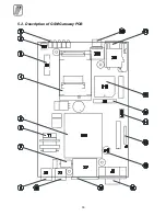
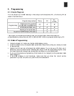
Explanatory Notes
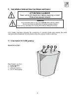
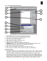
1. LED indicators
2. TL1 - Reset pushbutton
3. Lithium battery in holder
4. SIEMENS
®
GSM module TC35 or MC35
5. Mains transformer
6. PSTN line transformer
7. BJ1 - 2 x 10,000 A surge arrester – PSTN line first stage overvoltage protection
8. X6 – PBX line RJ-12 connector
9. X1 – PSTN line RJ-12 connector
10. X7 – mains supply connector
11. J2 – RS-232C serial interface connector
12. P1 - Mains fuse – T 200 m A
13. JP1 - diagnostic connector of power part
14. U16 – EEPROM containing GSM Gateway programmed parameters
15. X8 - diagnostic connector of digital part
16. U10 – main micro controller in the socket
17. X9 – SIM card holder
18. Antenna connector
Notes:
•
The main microcontroller can be removed with a specialized tool only. Usually, it is not
necessary because the microcomputer can be reprogrammed in the GSM Gateway. Using
another tool may cause damage to or destroy the PCB!
•
The main microcontroller contains a serial number of GSM gateway as well as a protected
code. If erased by a programming tool unlike GSM program, it will not work and these data
cannot be re-programmed by GSM program again!
Содержание ATEUS 501106E
Страница 2: ......
Страница 32: ...30 5 2 Description of GSM Gateway PCB ...
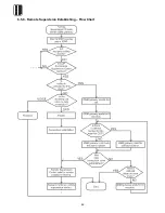
Страница 44: ...42 6 5 8 Remote Supervision Establishing Flow Chart ...
Страница 66: ......
Страница 67: ... 2004 2N TELEKOMUNIKACE a s Prague DR 1101 v 1 1 ...


