background image

Network Video Recorder | Installation Manual

12 

Copyright


© 2015 Nortek Security & Contro

l

!CAUTION!

•  Keep the device away from heat sources such as radiators, electric heaters, or 
other heat equipment.

•  Keep the device away from moist, dusty, extremely hot or cold places with 
strong electric radia  on.

•  Strictly observe installa  on requirements when installing the device. The 
manufacturer shall not be held responsible for device damage caused by users’ 
non-conformance to these requirements.

•  Strictly conform to local electrical safety standards and use power adapters 
that are marked with the LPS standard when installing and using this device. 
Otherwise, this device may be damaged.

•  Use accessories delivered with this device. The voltage must meet input 
voltage requirements for this device.

•  When device is in use, ensure no water or any liquid 

fl

 ows into the device. If 

water or liquid unexpectedly 

fl

 ows into the device, immediately power o

  the 

device and disconnect all cables (such as power cables and network cables) from 
the device.

•  Do not focus strong light (such as lighted bulbs or sunlight) on this device. 
Otherwise, the service life of the image sensor may be shortened.

•  If this device is installed in places where thunder and lightening frequently 
occur, ground the device nearby to discharged high energy such as lightening 
strikes in order to prevent device damage.

•  Avoid heavy loads, intensive shakes, and soaking to prevent damages during 
transporta  on and storage. The warranty does not cover any device damage 
that is caused during secondary packaging and transporta  on a  er the original 
packaging is opened.

•  Protect this device from dropping and intensive strikes, keep the device away 
from magne  c 

fi

 eld interference, and do not install the device in places with 

shaking surfaces or under shocks.

•  Clean the device with a so   dry cloth.

•  Do not block or penetrate ven  la  on opening with steel objects. Follow the 
installa  on instruc  ons provided in this document when installing the device.

REGULATORY INFORMATION

WARNING: Changes or modi

fi

 ca

Ɵ

 ons not expressly approved by Nortek Security 

& Control could void the user’s authority to operate the equipment.

This device complies with FCC Part 15 Rules and Industry Canada licence-
exempt RSS standard(s). Opera  on is subject to the following  two condi  ons: 
(1) this device may not cause interference, and (2) this device must accept any 
interference, including interference that may cause undesired opera  on of the 
device.
Cét appareil est conforme la norme d’Industrie Canada exempts de licence RSS. 
Son fonc  onnement est soumis aux deux condi  ons suivantes: (1) cét appareil 
ne peut pas provoquer d’interférences, et (2) c’et appareil doit accepter toute 
interférence, y compris les interférence, y compris les interférences qui peuvent 
causer un mauvais fonc  onnement de la disposi  f.

LIMITED WARRANTY

This Nortek Security & Control LLC product is warranted against defects in material 
and workmanship for two (2) years. This warranty extends only to wholesale 
customers who buy direct from Nortek Security & Control LLC or through Nortek 
Security & Control normal distribu  on channels. Nortek Security & Control does 
not warrant this product to consumers. Consumers should inquire from their 
selling dealer as to the nature of the dealer’s warranty, if any.
There are no obliga  ons or liabili  es on the part of Nortek Security & Control for 
consequen  al damages arising out of or in connec  on with use or performance of 
this product or other indirect damages with respect to loss of property, revenue, 
or pro

fi

 t, or cost of removal, installa  on, or reinstalla  on. All implied warran  es 

for func  onality, are valid only un  l the warranty expires. This Nortek Security & 
Control Warranty is in lieu of all other warran  es expressed or implied.

Nortek Security & Control LLC

1950 Camino Vida Roble, Suite 150
Carlsbad, CA 92008-6517 USA

For technical support in the USA and Canada:

855-2GIG-TECH (855-244-4832)
Email: [email protected]
Visit www.nortekcontrol.com for technical support hours of opera  on

For technical support outside of the USA and Canada:

Contact your regional distributor
Visit dealer.2gig.com for a list of distributors in your region

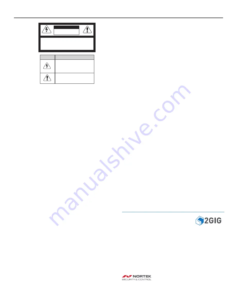
CAUTION

RISK OF ELECTRIC SHOCK

DO NOT OPEN

CAUTION: TO REDUCE THE RISK OF ELECTRIC SHOCK

DO NOT REMOVE COVER (OR BACK)

NO USER-SERVICEABLE PARTS INSIDE

REFER SERVICE TO QUALIFIED PERSONNEL

Symbol

Descrip  on

This symbol is intended to alert the user to 
presence of un-insulated “dangerous voltage” 
within the products enclosure that may be of 
su

  cient magnitude to cons  tute a risk of 

electric shock.

This symbol is intended to alerd the user to 
the presence of important opera  ng  and 
maintenance (Servicing) instruc  ons  in  the 
literature accompanying the device.

1004381X23

Содержание 2GIG-NVR1

Страница 1: ...eed Electric Drill Level for wall moun ng of NVR module Hard Drive Installation into NVR 1 Remove the two screws on the bo om of the Network Video Recorder housing Figure 2 Hard Disk Cover Removal 2 Pry up the hard disk cover to expose wiring harness for harddisk connec on 3 Fix the hard disk to the hard disk cover using 4 1 4 Phillips screws Provided with NVR Figure 3 Fixing Hard Disk to NVR Hard...

Страница 2: ...S DC power interface Connected to an external power adapter Figure 8 NVR Front Panel Component Plug Ins Wall Mounting NVR Optional If wall moun ng of NVR case is desired perform the following installa on procedures If not proceed to Figure 10 for plug in 1 Place paper template on wall a er removing backing in desired loca on NOTE A level may be needed for installa on 2 Using a 1 8 bit and variable...

Страница 3: ... POE 1 2 3 4 COM 1 1B 1A IN OUT VGA OR HDMI VIDEO OUTPUT MONITOR LAN HDMI VGA RESET LINE OUT MIC IN DC IN POE 1 2 3 4 COM 1 1B 1A IN OUT MIC INPUT AUDIO OUTPUT LAN HDMI VGA RESET LINE OUT MIC IN DC IN POE 1 2 3 4 COM 1 1B 1A IN OUT EXTERNAL POWER LAN HDMI VGA RESET LINE OUT MIC IN DC IN POE 1 2 3 4 COM 1 1B 1A IN OUT ALARM INPUT CONTACT SWITCH ALARM OUTPUT SIREN 5V LOAD LAN HDMI VGA RESET LINE OUT...

Страница 4: ...17 Ini alizing System Con nued Figure 18 Ini alizing Screen A er ini aliza on is complete the login screen appears as shown in Figure 13 Change the screen resolu on by clicking on the change link at the bo om Also screen output can be adjusted by clicking the adjust link Opera onal screen resolu on is 1024 x 768 or higher Place cursor in User Name block A keyboard will appear in the lower right co...

Страница 5: ...e 1 Default device name is 2GIG NVR 2 Click the bu on to the far right of the DEVICE TIME to open date and me window 3 In the DATE AND TIME window select TIME ZONE using down arrow to the far right 4 Set Daylight Savings Time by entering Start and End mes for DST in your region 5 Set Device Date and Time by edi ng the pop up menu 6 Set Date Format as desired 7 Click the GREEN CHECK MARK to Save ch...

Страница 6: ...and how much is le available If the HDD is shown as NOT USABLE the HDD is either unrecognized not installed properly or it needs to be forma ed To remove the HDD from the NVR click the UNLOAD bu on Power off NVR and remove the hard drive The NVR has four 4 PoE ports which is part of a private network which can be connected to IP cameras IP cameras can also be connected through LAN The number of IP ...

Страница 7: ...rd to 5 Stream specifies which IP Camera stream will be recording to the NVR Figure 30 Stream Setup 1 The Stream ID allows selec on of three different streams to configure 2 Use the Name op on to label each of the three streams 3 Use the Video Encode Type to set the H 264 profile High Profile is recommended 4 Use the Audio Encode Type to set the audio format G711_ULAW is recommended 5 Use Resolu on...

Страница 8: ... bar shows a graphical recording representa on of the selected IP Cameras Red highlights indicate Alarm recording mo on Green highlights indicate con nuous recording not alarms 5 To go to a specific me in the recording use the Focus Time op on 6 The Time Range allows expanding the me start and end points in the Timeline bar 7 The Select Video op on allows Backup of the Video to an external media s...

Страница 9: ...ct to the NVR Figure 37 Home Screen 4 Click on the icon to connect to the desired camera Figure 38 Live View 5 The func on bar allows you change layouts zoom in out enable audio and perform a snapshot 6 If you tap once on the image you can record video to your mobile device and switch streams To switch streams press the arrow icon on the le side of the live video stream Figure 39 Playback Reel Ico...

Страница 10: ...lect the Time list icon to bring up a list of recorded mes 12 Press the recorded playback icon to playback video from the NVR Select a camera to play back Android NVR App Quick Start Figure 42 2GIG NVR app icon 1 From the Google Play Store search for 2GIG NVR app 2 Install and launch the 2GIG NVR app Figure 43 Login Screen 3 Type in the Login creden als to connect to the NVR Figure 44 Camera List ...

Страница 11: ...hen logging into the router Q Can I port forward the same control port mulƟple Ɵmes A No Each device needs to have each unique Control Port If you have an NVR and mul ple IP Cameras each device will need its own control port which also needs to be forwarded in the router The 2GIG Video app and the 2GIG NVR app will use the WAN IP address and control ports to connect to your video devices from outs...

Страница 12: ...o the following two condi ons 1 this device may not cause interference and 2 this device must accept any interference including interference that may cause undesired opera on of the device Cét appareil est conforme la norme d Industrie Canada exempts de licence RSS Son fonc onnement est soumis aux deux condi ons suivantes 1 cét appareil ne peut pas provoquer d interférences et 2 c et appareil doit...

Отзывы: