MANUAL NO. SIEP S800000 66A
COSMOS以外(A4)(英文)新CI
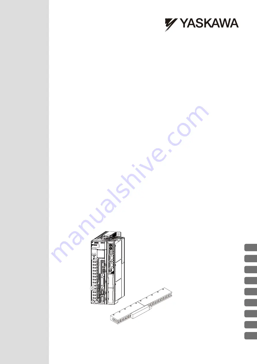
SGDV SERVOPACK
SGLGW/SGLFW/SGLTW/SGLCW/SGT Servomotors
Linear Motor
Command Option Attachable Type
Σ
-
V
Series
AC Servo Drives
USER'S MANUAL
Design and Maintenance
Outline
Wiring and Connection
Operation
Adjustments
Utility Functions (Fn
)
Monitor Modes (Un
)
Troubleshooting
Appendix
1
2
3
4
5
6
7
8
9
Panel Display and
Operation of Digital Operator