


Manufacturer/Supplier
Product Type
RPM
Cycles Per Min
Tel No
Fax No
(01494) 883300
(01494) 883237
Model No/Nos
Serial No
Product Nett Weight
lbs
Kg
Recommended Use Of
Balancer Or Support
Recommended Hose Bore
Size - Minimum
Recommended Max.
Hose Length
Ins
M/M
Ft
M
Foreseen Use of the Tool
This angle tool is designed for use with 7" diameter coated abrasive
discs of various grades of grit which are designed to be used at the
same or higher speed of this tool. The spindle thread is 5/8 - 11
UNC-2A and the tool can be used with other abrasive devices that
have the same female thread size and are designed to run without a
guard and have a rated speed equal to or higher than the speed of the
tool. Do not attempt to use any bonded abrasive devices, i.e. grinding
wheels, as those which could be fitted because of their size, cannot
be used without a suitable guard. A guard is not available for this tool.
Do not fit any form of saw blade.
Do not fit any other abrasive or cutting device before checking the
suitability for use with this tool with the manufacturer or the
manufacturer's authorised distributor.
Do not modify this tool for other use, or for its use as a
sander/polisher before checking the intended alternative use with the
manufacturer or his authorised distributor.
Putting Into Service
Air Supply
Use a clean lubricated air supply that will give a measured air pressure
at the tool of 90 p.s.i./6.3 bar when the tool is running with the
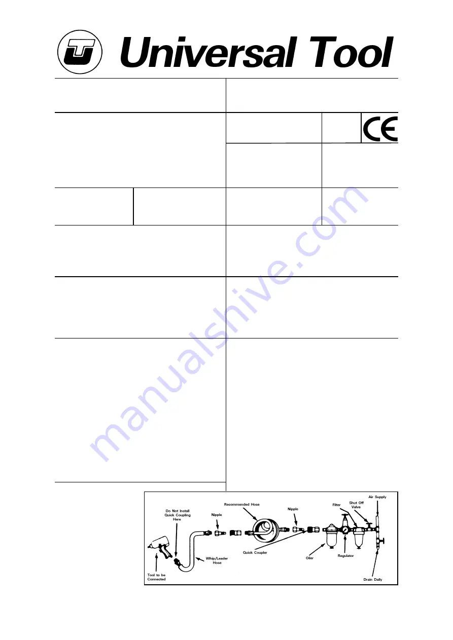
trigger/lever fully depressed. Use recommended hose size and
length. It is recommended that the tool is connected to the air supply
as shown in figure 1. Do not connect the tool to the air line system
without incorporating an easy to reach and operate air shut off valve.
The air supply should be lubricated. It is strongly recommended that
an air filter, regulator, lubricator (FRL) is used as shown in Figure 1 as
this will supply clean, lubricated air at the correct pressure to the tool.
Details of such equipment can be obtained from your supplier. If such
equipment is not used then the tool should be lubricated by shutting
off the air supply to the tool, depressurising the line by pressing the
trigger on the tool. Disconnect the air line and pour into the intake
bushing a teaspoonful (5ml) of a suitable pneumatic motor lubricating
oil preferably incorporating a rust inhibitor. Reconnect tool to air
supply and run tool slowly for a few seconds to allow air to circulate
Work Stations
The tool should only be used as a
hand held hand operated tool. It is
always recommended that the
tool is used when standing on a
solid floor. It can be used in other
positions but before any such use
the operator must be in a secure
position having a firm grip and
footing and be aware of the safety
rules to be obeyed when using
the sander/polisher.
No
Air Pressure
Recommended Working
6.3
bar
90
PSI
Recommended Minimum
n/a
bar
n/a
PSI
Maximum
7
bar
100
PSI
Personal Safety Equipment
Use - Safety Glasses
Yes
Use - Safety Gloves
Yes
Use - Safety Boots
Use - Breathing Masks
Yes
Use - Ear Protectors
Page No 1
7" Dia Pad Right Angle
Sander/Polisher
UT8751 - 4500 RPM
Angle Sander
UT8752 - 2400 RPM
Angle Polisher
5.0
2.3
3/8
10
30
10
(See Below)
Includes - Foreseen Use, Work Stations, Putting Into Service, Operating,
Dismantling, Assembly and Safety Rules
Operator Instructions
Important
Read these instructions carefully before installing, operating,
servicing or repairing this tool. Keep these instructions in a safe
accessible place.
Universal Air Tool Company Limited
Unit 8
Lane End Industrial Park
High Wycombe
Bucks
HP14 3BY
Noise Level
Sound Pressure Level 97.0 dB(A)
Test Method
Tested in accordance with Pneurop
test code PN8NTC1 and ISO Standard 3744
Sound Power Level 107.40 dB(A)
Vibration Level
Test Method
Tested in accordance with ISO
standards 8662/1 & 8662/4
Less than 2.5
Metres / Sec²


