background image

1

DO NOT START THE MACHINE BEFORE READING CAREFULLY THESE

INSTRUCTIONS

REMARK :

Wheel balancing machine TROLL 3100 isn”t equiped an automatic ultrasonic system measurement
geometrical parameters of balanced wheel. All description concern the  service this system, placed
in present manual instruction, arent conforming to this type machine.
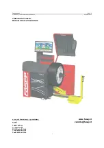
The balancing machine TROLL 3105  is provided


with an automatic measurement system geometric

for measuring parameters of the wheel balanced, start while closing the wheel guard. After closing

the guard the measuring cycle is started automaticaly.

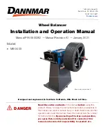
1 . APPLICATION AND TECHNICAL DATA

TROLL 3100 / 3105 balancing machine is designed for dynamic balancing of car and van wheels

in a single measurement  cycle.

TECHNICAL DATA :

  - max. wheel diameter

1,15 m

       - wheel diameter

 10”  - 24”

  - wheel width

2"   -   10"

       - accuracy of unbalance indications

1 g

       - accuracy of unbalance location signal

3 stages

       - measurement time

3 s

       - machine weight

ok. 145 kg

       - overall diamensions with closed shield:

1140x900x1150 mm

with open shield :

1140x1050x1450 mm

       - whell weight

do 60 kg

       - drive motor rating

0,25 kW

       - spindle spind ( during measurement )

230 r.p.m.

       - power supply

220 V / 50 Hz

  - air supply

0,6-1,0 MPa

The balancing machine TROLL 3100/3105  is equipped with a speach synthetiser, emitting

confirmations of each operation performed and suggesting procedures for whel balancing.

Indications quantity and position unbalance take reading on monitor measurement.

Programme „hiden weight” allows on the partition and the spacing of balancing slugs
on invisible spoken of alloy rim. Balancer is equiped an automatic stop at the top which
is blocking of wheel for both point of unbalancing. The brake release is seting after a
little displacement (ca. 3 grades) of wheel from shown unbalancing points or after press
the button on the keyboard which indicate a disapperation of  arrows.

2 . INSTALLATION

TROLL - 3100 / 3105  balancing machine should be installed in a closed, dry room, heated during

auttumn / winter season. The machine should be installed on a hard and levelled floor. The balancing

machine should be installed on three rubber pads, suppiled with the machine (item 28, fig. 2)

which should be inserted under the three flat feet welded to the machine base.

Summary of Contents for TROLL 3100

Page 1: ... open shield 1140x1050x1450 mm whell weight do 60 kg drive motor rating 0 25 kW spindle spind during measurement 230 r p m power supply 220 V 50 Hz air supply 0 6 1 0 MPa The balancing machine TROLL 3100 3105 is equipped with a speach synthetiser emitting confirmations of each operation performed and suggesting procedures for whel balancing Indications quantity and position unbalance take reading ...

Page 2: ...2 19 17 20 18 14 15 13 16 10 11 15 16 2 3 1 4 5 6 7 12 17 18 13 Buttons numbers 25 23 24 21 26 22 ...

Page 3: ...ary key 12 Balancing machine memory initiating key MEMEORY READOUT 13 Subrotine input key 14 Subrotine output key 15 Parameter change key increase 16 Parameter change key decrease 17 Cursor up key 18 Cursor down key 19 Cursor left key 20 Cursor right key 21 Balancing machine master switch 22 Printer 23 Socket to connect cabel lenght shield 24 Sensor run out measurement in programme minimisation 25...

Page 4: ...nd fixture 2 Install fixture so that markers 3 on spindle dowel and fixture are in the position shown in fig NOTE Thorough cleaning of taper surfaces and apprioprate position of fixture in relation to spindle markers coinciding is one of preconditions of correct wheel balancing Rys 2 Fittingfixturewithoutnit tapersandsleeves ...

Page 5: ...ange item 4 by means of four M8 bolts item5 passing through shield eye item 3 Connect guard cable item 6 to socket item7 The connected cable must not be strained while opening and closingthe guard it must be slack Unless the cable is connected the automatic start of the balancing machine will not possible NOTE In the machanism of the shiekd a dramper is provided to limit the opening and closing sp...

Page 6: ... 4 with the socket 5 a screw down The sensor may be mounted on the stand perpendicularly against the balancing machines side panel for the radial run out measuremant or parallel against the balancing machines side for the axial run out measurement The cabel 4 is located in the housing s rear panel The ultrasonic generator is located in the opening in the sensor is front panel NOTE The sensor is fr...

Page 7: ...HOURS NECESSARYFORDRYINGELECTRONICCOMPONENTSANDTOREACH ROOM TEMPERATURE FAILURE TO DO DO MAY CAUSE SERIOUS DAMAGE TO THE BALANCINGMACHINE 8 OPERATING BALANCING MACHINE COMPUTER 8 1 Switch balancing machine computer Switch machine master switch on as well as monitor power supply switch Balancing machine will emit announcement SYSTEM TEST and them SYSTEM OPERATIVE Atest pattern shall appear on monit...

Page 8: ...g by depressing keys Output from respective subroutine by depressing the key SELECT PROCEDURE will appear on the screen shown in Fig 5 8 3 Unbalance measurement Cursor guiding by depressing keys an position UNBALABCE MEASUREMENT Fig 5 and push button The computer will set in the subprogramme UNBALANCE MEASUREMENT the monitor will show the screen as per figure 6 After this subprogramme has been ini...

Page 9: ...ans of keys or setting in position 10 Balancing machine computer will br then programmed for manual start In this case parameters of the wheel to be balanced are entered to machine memeory as described in items 8 3 1 8 3 3 Above is concerning balancer TROLL 3105 Automatic start in balancer TROLL 3100 is setting other way The change of mode starting will be realized by simultaneous pressing the but...

Page 10: ...fig 7 b measure with a rule distance L between balancing machine wall and the rim of the wheel mounted in wheel chuck measurement in centimetre s multiply the measured value by four and subtract three according to formula DISTANCE 4 x L 3 8 3 2 Entering DIAMETER parameter manually Guide cursor to position 2 fig 6 over depressing key or by means of arrow 17 20 The machine will emit DIAMETER announc...

Page 11: ...11 Fig7b L DISTANCE Fig 7 a ...

Page 12: ...nner wheel rim edge alternative 4 balancing trough sticking one weight on the inside balancing plane and tapping another on the outer wheel rim edge alternative 5 static balancing for very thin wheel rims with one weight Not recommended for car wheels alternative 6 balancing trough sticking weights inside wheel rim alternative 7 balancing through tapping one weights on inside correction plane and ...

Page 13: ...ern Guide cursor by means of arrows to position 7 fig 6 and push button Measurement pattern shown in Fig 8 will be displayed on monitor screen 8 3 5 Entering Cut Off Threshold Value Guide cursor to position 5 fig 6 over push button or by means of arrow The balancing machine will emit THRESHOLD CHANGE Push button or cut off is changed 0g 2g 5g or 10g threshold may be set NOTE Entering cut off thres...

Page 14: ...as the capability of recording and storing parameters of eight different most frequently balanced wheels 8 4 1 Recording parameters in memory Guide cursor keys to position where data of a particular wheel are to be recorded Example recording wheel data of VOLVO car in position 1 Fig 9 Push button Computer will be set in DETERMINE SETTING VALUES subroutine and image shown in Fig 10 will appear on t...

Page 15: ...In silimar manner programme WHEEL DIAMETER in pos 3 WHEEL WIDTH in pos 4 WHEEL TYPE in pos 5 and MEASUREMENT ACCURACY in pos 6 By pushing button this data are entered to computer memory what is conform by announcement MEMORY RECORDING On monitor screen image shown in Fig 9 will appear with name VOLVO 8 5 Heading Edit Input to PROCEDURE SELECT subroutine by pushing button Guide cursor with keys to ...

Page 16: ...he works name adress phone After settingin each position store them in memory by pushing button Output from respective subroutine by pushing button 8 5 2 Setting time Push button guide cursor to position 5a Fig 11 Buttons set hour Push button guide cursor to position 5b Buttons set minutes 8 5 3 Setting data Setting data is similar to setting time Set date in c month in d year in e item1 item2 ite...

Page 17: ...ing button 8 6 Measurement counter Enter SELECT PROCEDURE subroutine by pushing button Guide cursor with keys to position MEASUREMENT COUNTER and press The computer will be set in MEASUREMENT COUNTER subroutine and image shown in Fig 12 will appear on monitor screen Fig 12 ...

Page 18: ... the balancing machine to prevent distortion of measurement by mud particles 9 1 1 Quick release fixture Type QUICK TROL quick release fixture is intended for mounting car on a van wheels with central hole wheel rims on balancing machines FIXTURE COMPONENT PARTS Fig 13 1 Hub 2 Bolt for mounting fixture to balancing machine spindle 3 Spring 4 Clamping nut 5 Centering taper No 1 6 Centering taper No...

Page 19: ...lever moves in relation to nut body within limits detrmined by slot in nut body positions L and D In position L loose the nut may be freely moved along fixture rod thread In position D clamp the nut may be screwed onto fixture rod thread ...

Page 20: ... as it will go Resting thumb on nut pin as shown in Fig 15 move lever to the right to position CLAMP and tighten nut preesing the whell against fixture disc Fig 15 Tightening nut in order to remove wheel from fixture rest index finger on nut pin as shown in Fig 16 and loosen nut by one half turn It may be then slid off the rod and the wheel may be removed from fixture Fig 16 Loosening nut ...

Page 21: ... user has the following options 1 to user taper No 1 2 with centering from the inside of wheel rim fixture nut should have pressure ring in place 2 to user taper No 1 2 with centering from the outside of wheel rim as shown in Fig 17 nut wthout pressure ring 3 to use centering disc No 1 or 2 as shown in Fig 18 nut without pressure ring Fig 17 Fig 18 Fig 19 ...

Page 22: ... tapers are used for mounting the wheel if cente red from the outside of wheel rim remove pressure ring from the nut In order to remove the pressure ring from the nut pull the pressure ring axially so that it falls off the detent To install pressure ring push it onto nut detent ...

Page 23: ...is started automatically measures unbalance values stops the wheel and displays measurement results in items 8 3 1 8 3 3 item 8 3 4 select balancing programm item 8 3 5 entering cut off threshold value 9 3 Entering measurement settings from computer memory manual start only If a wheel whose parameters were recorded in the computer memory ealier see item 8 7 1 is to be balanced then push button Com...

Page 24: ...kly the machine will not start Measurement of unbalance data if balancing machine has been programmed for manual start closing the wheel guard and pushing button If wheel guard is remove it spindle drive will be started after pushing button and the same time push button Working cycle is performing without operator s interference until the projection on indicators the value of unbalancing and autom...

Page 25: ...splayed on displays 3 and 4 is applicable to outside correction plane i e wheel rim edge closer to fixture nut Value of 25 displayed on display 1 informs about the need to tap a 78 g weight to the inner edge of the rim in order to balance the wheel that means for the purpose of liquidate unbalance on inside balancing plane nailed the weight a 25 g an on outside plane nailed the weight 80g 1 3 2 4 ...

Page 26: ...os should be displayed meaning that resiude unbalance does not exceed 5g according to the assumed cut off threshold In practice it does not have to be so Why Firstly balancing weights irrespective of type are made to some weightc tolerance Secondly the balancing machine measures the unbalance value to 2g and the unbalance location to 3 Thirdly a balancing weights is not a concetrated mss but has a...

Page 27: ...f unbalance coincidens with the old one or is lose to it 1 weight 2 new correction plane REDUCE WEIGHT if the new location of unbalance is directly opposite the weight fixed previously or is close to this point 1 weight 2 new correction plane ...

Page 28: ...ht of the new correction point 1 weight 2 new correction point It is difficult to determine precisely by what distance a weight should be shifted in order to correct such residue unbalance This depends on the size of weight fixed and also on the unbalance value to be corrected In general terms a larger weight requires less shift correction and also a small reside unbalance requires a small shift c...

Page 29: ...election of appoprite balancing method e g both weights stick on results in the balancing machine taking into account the change in weight fixing points on respective correction planes different from those resulting from the entered data Stick on weights must not be removed and replaced Therefore after unblance value has been displayed stuck always a weight 5 10 g lighter than that indicated by th...

Page 30: ...ted in the space between spokes and it is desired that the weight is invisible from outside the wheel By means of this programme the unbalance value shown on display 3 Fig 24 may be split between two balancing weights to be stuck at the back of two spokes situated at the least distance from the point of unbalance Procedure for Concealed Weight programme 1 Select version 6 or 7 of the balancing pro...

Page 31: ...s 9g unbalance point situated at the tompost point of the wheel rim d from this position rotate the wheel anticlockwise until the nearest spoke reaches vertical position and depress key The machine computer will remember this wheel position as the fixing point of the first weight and at the same time subsequent measurement pattern will appear on monitor screen as shown in Fig 26 Window I Window II...

Page 32: ...d in items 4c and 4d the wheel is rotated by mistake in the same direction balancing machine computer will indicate the fixing point of the second weight on the opposite side of the wheel If however the same spoke is located twice letters ddd will appear in windows II and III which always indicate an error in performance of the balancing programme In both cases Concealed Weight programme mast repe...

Page 33: ...ress push button On the screen should appear inscription Fix pic 10 Inlines 2 6 had wrote parameters balanced wheel which were transfered from balancing program 4 With the aid push buttons or operator select position 1 and should wrie according to procedure see point 8 4 1 yours characteristic data F E first name REMARK User can input to memory a characteristic data with the aid a program MULTIUSE...

Page 34: ...n monitor screen stating unbalance point and value Remove wheel rim from chuck fit tyre and inflate to specified pressure Mount complete wheel in balancing machine chick in the same position as wheel rim alone was installed i e valve should face markers on chuck and spindle Push button Image TYRED WHEEL MEASUREMENT will appear on monitor screen Depress again START key balncing machine drive will s...

Page 35: ...35 NOTE In the case when optimisation gains 0g the position of the tyre in respect of wheel rim is optimum Fig 28 1 2 ...

Page 36: ...ensor from wheel or wheel rim surface so that sensor position indictor visible on the screen Fig 29 as a verticaly line is near the centre of sensor positioning area Then rotate the wheel by hand a chime will signal the commencement of run out measurement On monitor screen message WHEEL RUN OUT MEASUREMENT IN PROGRESS will appear continue to rotate the wheel always in the same direction until chim...

Page 37: ... reaches the topmost point of the wheel symbol a sound signal will be heard then In a similar way the point of max run out towards the wheel centre is located 9ball 1 should reach the topmost point of the wheel symbol Depress key Image shown in Fig 31 will appear on monitor screen Fig 31 1 2 min max ...

Page 38: ...in balancing machine chuck so that the valve is directly opposite the markers on chuck and spindle Depress key TYRE RUN OUT MEASUREMENT will appear on monitor screen to be replaced after a while with SET SENSOR Set sensor as described in section II Rotate whell so that chime is heard and TYRE RUN OUT MEASUREMENT is displayed on the screen Rotate wheel further until chime signalling the end of yhe ...

Page 39: ...39 Fig 32 NOTE In the case when minimisation gains O mm the position of the tyre in relation to the wheel rim is optimal ...

Page 40: ...board see items 8 3 1 8 3 3 Enter distance by means of edge finder pushing it against wheel rim edge Set cut off threshold to minimum value i e 2g May be automatic start 2 Tab a weight of 80 g anywhere on the outer edge of wheel rim 3 Push button or automatic start The measuring cycle ends with automatic braking of the balancing machine spindle and display 1 0 and display 2 79 or 80 Fig 33 NOTE Ap...

Page 41: ...re unbalance values of a car wheel or substantial indication differences in susequent measurements of the same wheel it is absolutely necessary to dry the main electronic board of the balancing machine Removal of the cover and drying the main board with e g a hair dryer does not make the warranty invalid Moisture most frequently appears during changing weather conditions auttum winter and winter s...

Page 42: ... unbalance in one plane e g 90g and a minor one in another plane e g 10g we recommended to fix a 90g weight only and to repeat the measurement as it may happen that after balancing the worse plane the unbalance value of the other plane will drop below 10g value measured previously If the unbalance is more than 100g fix a large weight e g 80g 90g 1000g and shift it several centimetres from the poin...

Page 43: ...m Selection 10 8 3 5 Entering Cut Off Threshold Value 13 8 3 6 Voice Volume Adjustment 13 8 3 7 Change of measurement Pattern 13 8 4 Setting Edit 14 8 4 1 Recording parameters in memory 14 8 5 Heading Edit 15 8 5 1 Recording heading Edit 16 8 5 2 Setting Time 16 8 5 3 Setting Data 16 8 6 Measurement counter 17 9 WHEEL BALANCING INSTRUCTIONS 18 9 1 Mounting the wheel on the balancing machine 18 9 1...

Reviews: