


Summary of Contents for VIDEOTRONIC V788.G3
Page 43: ......
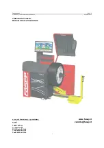
The Fasep VIDEOTRONIC V788.G3 is a revolutionary automotive diagnostic tool designed to streamline your workflows. With its comprehensive user manual available for free download at manualshive.com, you'll have all the necessary information to maximize the potential of this cutting-edge device. Seamlessly navigate through its features and optimize your automotive diagnostic experience with ease.
Page 43: ......