


1645 Lemonwood Dr.
Santa Paula, CA 93060 USA
Tel: (877) 432-6627
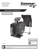
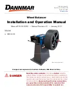
Wheel Balancer
Installation and Operation Manual
Manual P/N 5900262 — Manual Revision A1 — January 2021
Designed and engineered in Southern California, USA. Made in China.
⚠
DANGER
Read the
entire
contents
of this manual
before
using this
product. Failure to follow the instructions and safety precautions in
this manual can result in serious injury or death. Make sure all other
operators also read this manual. Keep the manual near the product
for future reference.
By proceeding with setup and operation,
you agree that you fully understand the contents of this
manual and assume full responsibility for product use.
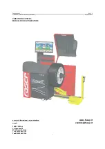
Model:
MB-240X
Shown with optional stand.
Summary of Contents for MB-240X
Page 46: ...MB 240X Wheel Balancer 46 P N 5900262 Rev A1 Jan 2021 Figure H...
Page 47: ...MB 240X Wheel Balancer 47 P N 5900262 Rev A1 Jan 2021 Wiring Diagram 220 V Power Board...
Page 48: ...MB 240X Wheel Balancer 48 P N 5900262 Rev A1 Jan 2021 Labels...
Page 49: ...MB 240X Wheel Balancer 49 P N 5900262 Rev A1 Jan 2021 D...
Page 58: ...MB 240X Wheel Balancer 58 P N 5900262 Rev A1 Jan 2021 Maintenance Log...
Page 59: ...MB 240X Wheel Balancer 59 P N 5900262 Rev A1 January 2021 Maintenance Log...
Page 60: ...1645 Lemonwood Drive Santa Paula CA 93060 USA 2021 BendPak Inc All rights reserved Dannmar com...