


I 09
92
- 04/15 - Ver. 07
ENGLISH
Use and maintenance manual
GB
WHERE AND HOW TO KEEP THE MANUAL
MANUFACTURER’S RESPONSIBILITY AND WARRANTY
3.4.1
Periodic cleaning
13
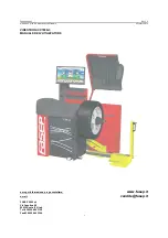
The Hoffmann Megaplan Megaspin is a cutting-edge tire balancing machine, designed to deliver exceptional performance and accuracy. To help users make the most of this advanced equipment, we offer a comprehensive Use and Maintenance Manual. Download this manual for free at manualshive.com to ensure optimal functionality and longevity of your Megaspin machine.
I 09
92
- 04/15 - Ver. 07
ENGLISH
Use and maintenance manual
GB
WHERE AND HOW TO KEEP THE MANUAL
MANUFACTURER’S RESPONSIBILITY AND WARRANTY
3.4.1
Periodic cleaning
13