


Summary of Contents for 8118/1 Series
Page 49: ......
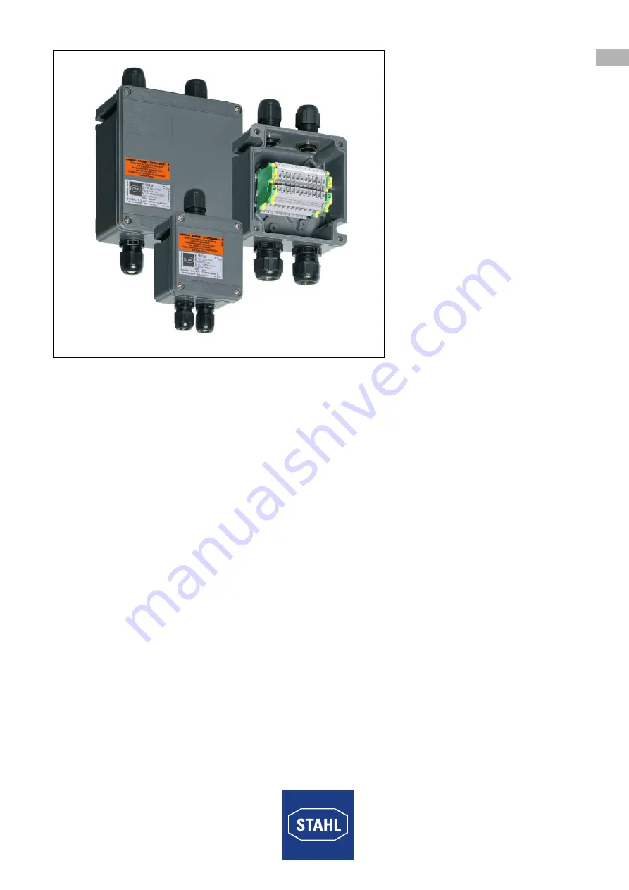
The Stahl 8118/1 Series offers high-performance functionality in a sleek design. Ensure you are maximizing its features with the Operating Instructions Manual, available for free download from our website. This comprehensive manual will guide you through setup and operation, ensuring optimal performance of your Stahl 8118/1 Series product.
Page 49: ......


