Union Community AC-6000, Installation And Wiring Manual
The Union Community AC-6000, a cutting-edge security access control system, is seamlessly installed and wired using the comprehensive "Installation and Wiring Manual." This essential manual is available for free download on our website, empowering users to maximize the potential of their AC-6000 system.
Share
Download


Reviews:
No comments
Related manuals for AC-6000

MX8800
Brand: Nautilus Hyosung Pages: 827

AMP 100
Brand: Infinite Peripherals Pages: 16

VXT 2000 Model VX225
Brand: Digital Equipment Pages: 42

GS220
Brand: GIETEK Pages: 34

FieldPoint FP-TB-10
Brand: National Instruments Pages: 22

BEETLE /iPOS plus Advanced
Brand: Wincor Nixdorf Pages: 73

DP200 Series
Brand: Sauer Danfoss Pages: 12

ASA1222G-D
Brand: Dahua Pages: 22

Worldline YOMANI TOUCH XR AUTONOM
Brand: SIX Payment Services Pages: 22

LP-RU07KVXX
Brand: Lanpro Pages: 16

AerPOS AP-3617
Brand: FEC Pages: 49

M215SE
Brand: ACD GRUPPE Pages: 65

Ingenico ICT250
Brand: Chase Pages: 10

GT2510-WXTBD
Brand: Mitsubishi Electric Pages: 2
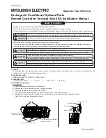
PAC-SH29TC-E
Brand: Mitsubishi Electric Pages: 2

VL100
Brand: Valor Pages: 2

FlexiPole Complete
Brand: Tailwind Pages: 2

Optima
Brand: Almex Pages: 10


