background image


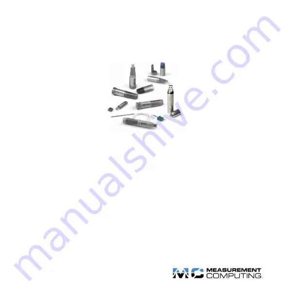
USB-500 Series 

Quick Start & Reference Guide 


Contents 


System requirements and recommendations ..........................................................................................................................................2


USB-501-PRO Safety Agreement ......................................................................................................................................................... 3


Installing the software ............................................................................................................................................................................4


Installing USB-500 Series Data Loggers ...............................................................................................................................................5


Running the USB-500 Data Logger Application and Help....................................................................................................................5


USB-501 LED functions ........................................................................................................................................................................6


USB-501-TC, USB-501-TC-LCD, and USB-501-RCG LED functions ...............................................................................................7


USB-501-TC-LCD display ....................................................................................................................................................................8


USB-501-LT LED functions ..................................................................................................................................................................9


USB-502 and USB-502-PLUS LED functions ....................................................................................................................................10


USB-502-LCD LED functions .............................................................................................................................................................11


USB-502-LCD display .........................................................................................................................................................................12


USB-503 and USB-504 LED functions ...............................................................................................................................................13


USB-505 LED functions ......................................................................................................................................................................14


Battery safety and power-saving guidelines .........................................................................................................................................15


Replacing the battery............................................................................................................................................................................16


Recharging the USB-501-RCG battery ................................................................................................................................................19


How to contact technical support .........................................................................................................................................................19


Summary of Contents for USB-500 Series

Page 1: ...Help 5 USB 501 LED functions 6 USB 501 TC USB 501 TC LCD and USB 501 RCG LED functions 7 USB 501 TC LCD display 8 USB 501 LT LED functions 9 USB 502 and USB 502 PLUS LED functions 10 USB 502 LCD LED functions 11 USB 502 LCD display 12 USB 503 and USB 504 LED functions 13 USB 505 LED functions 14 Battery safety and power saving guidelines 15 Replacing the battery 16 Recharging the USB 501 RCG batte...

Page 2: ...er Application software before plugging your USB 500 Series data logger into a USB port on your computer Notice Measurement Computing Corporation does not authorize any Measurement Computing Corporation product for use in life support systems and or devices without prior written consent from Measurement Computing Corporation Life support devices systems are devices or systems which a are intended ...

Page 3: ...ts The logger is metal and will retain heat or will remain cold when it has been removed from the environment under measurement Personal protection such as suitable heat resistant gloves or tools must be used to remove the logger from any environment Refer to the product specifications for the maximum and minimum temperatures in which the logger can be used 2 Replacing batteries Always operate the...

Page 4: ...lowed by a Welcome dialog that starts the USB 500 Data Logging Application installation program 2 Click Next A Destination Folder dialog opens To install the software in the default folder click Next To install the software in a different folder click Change button enter the new location on the Change Current Destination Folder dialog click OK button and then click Next A Ready to Install the Prog...

Page 5: ...lick Install the software automatically and then click Next Another Found New Hardware Wizard dialog opens while it searches for the software Once the software is found the last Found New Hardware Wizard dialog opens telling you the installation is complete 3 Click Finish Running the USB 500 Data Logger Application and Help To run the USB 500 Data Logger Application select Programs Measurement Com...

Page 6: ...01 is logging with a high alarm The action you take depends on your application If both alarms have Hold selected the LED only applies to the first alarm condition detected Red green and amber LEDs When the amber LED flashes concurrently with the red or green LED the USB 501 s memory is full and it can store no more readings An alarm condition is indicated by the green or red LED You need to downl...

Page 7: ...es once every 10 seconds the device is logging with a low alarm The action you take depends on your application When the red LED flashes twice every 10 seconds the device is logging with a high alarm The action you take depends on your application When the red LED flashes once every 20 seconds the battery charge is low and it has a low alarm but it continues logging Replace the battery and downloa...

Page 8: ... displays the status of the logging indicators Refer to the table below for an explanation of the logging status indicators LCD status icon Logger status Explanation Delayed start Displays when the logger is configured to start logging at a specific date and time If the LCD is configured to display for 30 seconds after the button is pressed then this will only be shown after the LCD button is pres...

Page 9: ... flashes red once the USB 501 LT is logging with a low alarm The action you take depends on your application When you press the LED button and the LED flashes red twice the USB 501 LT is logging with a high alarm The action you take depends on your application If both alarms have Hold selected the LED only applies to the first alarm condition detected No LED When you press the LED button and the L...

Page 10: ...e every 10 seconds the USB 502 502 PLUS is logging with a high alarm The action you take depends on your application When each LED alternately flashes red three times every 10 seconds both readings have an alarm condition and the logger s memory is full and can store no more readings You need to download data from the device When both LEDs flash red simultaneously once every 60 seconds the logger ...

Page 11: ...shing green LED indicates that no alarm condition has been logged during the current logging session Red LEDs When a red LED flashes once every 10 seconds the USB 502 LCD is logging with a low alarm The action you take depends on your application When a red LED flashes twice every 10 seconds the USB 502 LCD is logging with a high alarm The action you take depends on your application When a red LED...

Page 12: ...umidity rh Minimum stored relative humidity rh The LCD also displays the status of the logging indicators Refer to the table below for an explanation of the logging status indicators LCD status icon Logger status Explanation Delayed start Displays when the logger is configured to start logging at a specific date and time If the LCD is configured to display for 30 seconds after the button is presse...

Page 13: ... with a low alarm The action you take depends on your application When the red LED flashes twice every 10 seconds is logging with a high alarm The action you take depends on your application When the red LED flashes once every 20 seconds the USB 503 USB 504 s battery charge is low and it has a low alarm but it continues logging Replace the battery and download data When the red LED flashes twice e...

Page 14: ...charge is low The device continues logging but alarm conditions are ignored You need to replace the battery When the green LED flashes twice every 20 seconds the USB 505 s memory is full and no alarm condition You need to download data from the device Red LED Red LED When the red LED flashes the USB 505 is logging an event state change or count No LEDs No LEDs When no LEDs are flashing plug the US...

Page 15: ...um battery o The USB 501 LT uses a CR1620 lithium button cell battery Be careful when handling batteries to avoid damaging the battery casing in any way Keep batteries away from heat and do not try to recharge them Follow local regulations when recycling or disposing of batteries Keep batteries out of reach of children A USB 500 Series data logger that is connected to the USB port uses more batter...

Page 16: ... down too far to avoid damaging the tab 3 While the tab is pushed down carefully pull apart the two sections of the data logger 4 Remove the old battery and dispose of it in accordance with local regulations Heed any warnings on the battery casing 5 Insert a new AA battery in the battery compartment Make sure the battery is aligned to the correct polarity symbols in the compartment 6 Slide the two...

Page 17: ...ttery is discharged or replaced the data logging process will however be stopped and cannot be re started until the battery has been replaced and the logged data has been downloaded to PC Caution The 3 6 V AA lithium battery supplied with the USB 501 PRO is rated for use in high temperatures and has the correct battery terminals Using a different battery type may result in fire or explosion at hig...

Page 18: ...ircuit board 4 Remove the circuit board from the housing 5 Remove the old battery by pushing in the direction of the arrow on the battery guard Dispose of the old battery in accordance with local regulations Heed any warnings on the battery casing 6 With the positive terminal facing away from the circuit board slide a new CR1620 lithium battery beneath the battery guard 7 Place the circuit board o...

Page 19: ...ically low warning the USB 501 RCG has stored any readings taken and safely shut itself down No more readings are logged and you must recharge the battery Caution Do not try to open the logger to replace the battery Do not use any source other than a standard USB port to recharge The battery starts recharging when connected to an active USB port and indicates it is recharging with a solid red LED ...

Page 20: ...HM USB 500 QS Ref doc Document Revision 13 January 2011 325168D 01 ...

Reviews: