NOVUS AUTOMATION
1/6
LogBox-AA
ELECTRONIC DATA LOGGER – MANUAL V1.1x H
PRESENTATION
LogBox-AA
is an electronic data logger with two analog input
channels. The values measured by these channels (data) are stored
in the logger electronic memory and later sent to a computer in table
or graphical form. It is possible to export them for use in programs
such as spreadsheets.
To configure the logger and view or download data, you must use the
NXperience
software. When you configure it, you can set the start
and end mode of the recordings, the parameters of each input,
among other functions.
LogBox-AA
provides an
auxiliary electronic switch
, which can be
used in series with the power supply of external instruments,
connected to the logger. With this feature, you can configure the
logger to close the switch and power these instruments only at the
instant of acquisition, extending the battery life of the external
instrument.
MEMORY CAPACITY
•
64 k Model:
It allows up to 64,000 logs.
The memory capacity is divided between the enabled channels.
When there are two enabled channels, each has half of the available
memory. When a single channel is enabled, it has all the memory at
its disposal.
The available memory capacity is indicated on the identification label,
attached to the housing of the logger:
Figure 1 –
Identification label
INPUT SIGNALS
Input channels 1 and 2 of the logger measure the following analog
electrical signals: Pt100, Thermocouple (J, K, T, E, N, R, S or B),
voltage (0 to 50 mV or 0 to 10 V) or current (0 to 20 mA or 4 to 20
mA), depending on the configuration made.
Note:
In addition to performing the configuration via software, you
must properly position the internal jumper.
DATA ACQUISITION (LOGGING)
The logger can: 1) Perform a single measurement within a defined
period and log the value read or 2) perform ten measurements in this
period and log in memory the average of the values read or log the
minimum value or maximum value measured.
OPERATION
In the
NXperience
software, which must be previously installed on
the computer to be used, you can configure logger operation mode
(see
configuration, you must use the
IR-LINK3 Communication Interface
(see
item).
Once the device has been configured and the electrical input
connections have been made, it is ready to measure and record the
signals applied to the input channels. Status indicators display the
current condition of the logger.
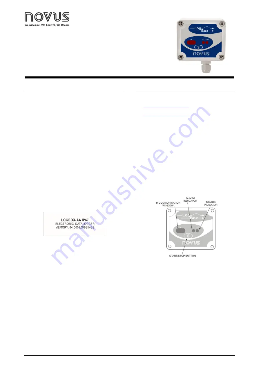
STATUS INDICATORS (LEDS)
The
Status Indicators
(see
Figure 2
), located on the front of the
logger, serve to indicate the current operating condition of the device:
LOG Indicator (Logging)
: If it is waiting to begin acquisitions
(stand-by) or after a series of acquisitions has been completed, the
LED blinks once every four seconds. If it is performing acquisitions,
it blinks twice every four seconds.
AL Indicator (Alarm)
: This indicator informs about alarm
situations. Whenever an alarm situation occurs, it blinks once
every four seconds. It remains in this condition until a new setting
is applied to the logger.
Figure 2 –
LEDs and IR communication