

NOTE: M1 firmware v5.2.8 or later is required in
order for Navigator to synchronize and display the
names of Areas, F Keys, Lights, Outputs, and Tasks.
ElkRP software v2.0.10 is recommended when
programming a M1 system that includes a Navigator.
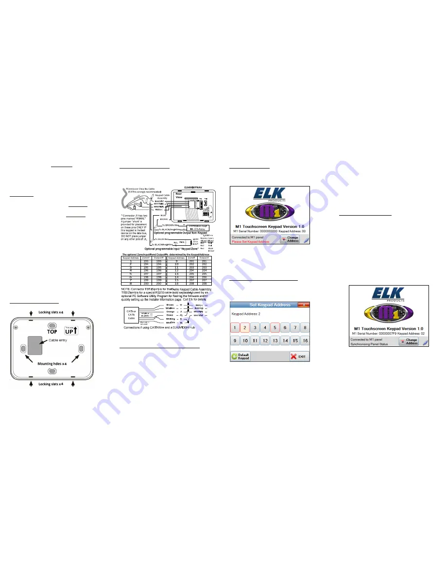
Mounting
Navigator can be wall mounted without a pre-wire
box. If a pre-wire box is used, it MUST BE a single
(1) gang electrical box designed for “New Work”, and
it should be installed sideways (horizontal).
Separate the Navigator front assembly from the
backplate by gently inserting a small flat blade
screwdriver into each of the four (4) locking slots one
at a time until the front releases. Be cautious when
handling the front assembly. Avoid touching or
damaging any exposed components. Do not bend or
pull on the flat ribbon cable that loops over the bottom
edge and plugs into the back of the board.
Insert data bus cable through marked entry. Position
backplate level on the surface with TOP facing up.
Install min. two screws in mounting holes provided.
Warning: Single gang electrical boxes designed for
“Old Work” have a wide outer trim dimension and
may not be suitable for use with Navigator. Installer
should test fit before installation!
Navigator Backplate
NOTE: An optional surface box (ELK-M1BBKN) is
available for use on concrete or block (non-hollow)
surfaces, or where wire raceway is needed.
Wiring Connections
Splice the four (2) wires on the plug-in cable to the
Data Bus Cable wire from the Control. Use “B”
connector splices or solder and tape the connections.
Re-attaching Front to Backplate
Plug the 6-wire cable assembly into connector TB1 on
the board. The polarity ribs should face the side gap.
When removing this cable, always grip the connector
body itself. DO NOT TUG OR PULL on the wires.
Tuck loose cable and splices out of the way.
Position the bottom edge of Navigator inside the lower
ledge of the backplate, and then rotate the top back
towards wall. Gently press until the 4 snaps engage in
the slots. DO NOT FORCE! If units do not snap
together, start over double checking for any loose
wires of connections which may be interfering.
Start-Up Screen
On power up the Start-up screen displays the Keypad
Version, M1 Serial number, and the Keypad (data bus)
Address
IF
one is currently set.
It an address is not set it will display “Please Set
Keypad Address”. If “Waiting to connect to panel” is
displayed then a data bus enrollment needs to be
performed from an already enrolled keypad.
Change (Set Keypad) Address
Each Keypad connected to an M1 must have its own
address, unique to any other keypad(s) on the system.
Press “CHANGE ADDRESS” on the Start Up screen
to bring up the Set Keypad Address screen.
NOTE: If the Main User Screen is displayed then
pressing and holding the “CLEAR” key for 15
seconds will bring up the Set Keypad Address screen.
The current keypad address will be illuminated. Any
address(s) with a RED border indicate a keypad
currently enrolled to the M1 panel. RED bordered
addresses CANNOT be used for this keypad.
Press any unused keypad address button to select that
address for this new keypad.
Default Keypad - Pressing the “Default Keypad”
button will clear the keypad address, M1 serial
number enrolled into the panel, function key names,
task names, lighting names and output names and area
names. It will not clear installer information.
EXIT – Pressing this button or the Red “X” in the top
right corner will exit the Set Keypad Address screen.
Data Bus Enrollment
A message “Please enroll keypad into panel” will
display if the keypad address does not match an
address currently enrolled in the M1, or has never
previously been enrolled into any M1.
Perform a Bus Enrollment using an already enrolled
keypad OR the ElkRP Remote Program software.
Once the keypad receives valid data from the M1
panel (and is enrolled) it will display the message
“Synchronising Panel Status”.
The Start-up screen displays until all current status
data is collected from theM1 panel. Once this is
complete the keypad will move on to the following
MAIN USER screen.


