1
A-100
INDOOR STAINLESS STEEL KEYPAD
WIRING & PROGRAMMING INSTRUCTIONS
WI1495 7/06
GENERAL DESCRIPTION
The A-100 is a self-contained access control keypad de-
signed for indoor basic access applications. Its heavy
stainless steel faceplate is designed to mount on a standard
single-gang electrical box. The A-100 operates up to three
outputs (two relays and 1 open-collector transistor) and can
be used to trigger a door strike, an electromagnetic door
lock, or any other relay-activated device. Programming is
performed manually at the keypad, allowing up to 150 indi-
vidual Users, each with their unique User Codes. The A-
100 Series includes the rugged sealed environment A-
100WP (see WI1496) and the waterproof A-100IMWP (see
WI1497) mullion keypad with illuminated keys.
In a typical application, the A-100 will energize one or both
relays upon the keypad entry of a valid User Code. Outputs
1 and 2 are two relays of the three contact Form C type,
and Output 3 is an open collector transistor (terminal la-
beled "OC") that switches "on" (closes with the ground ter-
minal) when energized. The length of time the outputs are
energized (their "activation duration") can be programmed
to between 1 and 99 seconds. A Request-to-Exit button will
momentarily short Output 1 by wiring terminals M and P1
using a normally-open momentary-close switch.
To program the keypad functions you must first perform the
initial startup procedure, then enter
Program Mode
by
pressing the Master Code at the keypad. Once in Program
Mode, all system functions can be accessed and pro-
grammed. Exit Program Mode to put the keypad (with its
new programming) into use.
SPECIFICATIONS
•
12 to 24VDC (polarized) or 12 to 24VAC voltage input
•
Output 1: 5A/250VAC relay
•
Output 2: 3A/125VAC relay
•
Output 3: 250mA open collector
•
Capacity of 150 User Codes of 3 to 6 digits
•
Output activation duration programmable from 01-99 sec-
onds (program "00" to select "toggle" mode)
•
All programming stored in non-volatile EEPROM memory
•
Orange LED Keypress feedback
•
Output #1 relay activation duration programmable per user
code
•
Tamper switch output terminals (S1 - S2) on PCB
•
Sounder "beeps" can be activated or deactivated for user
code entries
•
Operating Temperature: -13°F to 131°F
-25°C to +55°C
•
Dimensions (WxHxD): 3" x 4
3
/
8
" x
7
/
8
"
7.6cm x 11.1cm x 2.2cm
•
Operating Voltage: 12VDC to 28VDC
10VAC to 26 VAC
•
Maximum Current Draw:
12VDC: 13mA (Standby) 48mA (Active)
24VDC: 20mA (Standby) 58mA (Active)
12VAC: 30mA (Standby) 100mA (Active)
24VAC: 50mA (Standby) 121mA (Active)
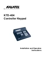
A-100 Wiring Table
Terminal Markings
Description
+
+ 12V or 24V AC/DC Input
–
– Ground
M
Request to Exit Input
P1
Request to Exit Input
OC
Open Collector Output
NO
Relay 1 Normally Open
C1
Relay 1 Common
NC
Relay 1 Normally Closed
NO
Relay 2 Normally Open
C2
Relay 2 Common
NC
Relay 2 Normally Closed
S1
Tamper SW Output
S2
Tamper SW Output
NO C2
C1 NC
NC
NO
M P1 OC
+
–
– G
ro
un
d
R
eques
t to Ex
it I
nput
R
eques
t to Ex
it I
nput
O
pen Colle
ctor Out
put
N
or
m
ally
O
pen Relay 1
Co
m
m
on
Re
la
y
1
Norm
all
y Clo
se
d Re
lay
1
No
rm
ally
O
pe
n R
ela
y 2
Co
m
m
on
Re
la
y
2
Norm
all
y Clo
se
d Re
lay
2
S2 S1
Tamper SW Output
Tamper SW Output
A-100
Keypad
+ 12V or
2
4V AC
/DC
Inpu
t
345 Bayview Avenue
Amityville, New York 11701
For Sales and Repairs 1-800-ALA-LOCK
For Technical Service 1-800-645-9440
Publicly traded on NASDAQ Symbol: NSSC
© ALARM LOCK 2006