background image

Summary of Contents for KA-4

Page 1: ......

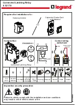
Page 2: ...41 923 4M 2 Figure 1 Type KA 4 Relay without case Front View ...

Page 3: ...ternal Schematic of the Type KA 4 Relay for TC Carrier Set Figure 4 Internal Schematic of the Type KA 4 Relay with Modified Carrier Stop to Terminal 11 for TC Carrier Set Figure 5 Internal Schematic of the Type KA 4 Relay for the TA 3 tones Sub 1 3491A17 Sub 1 349A16 Sub 3 629A389 Sub 9 629A476 ...

Page 4: ... operation of the sec ond zone or KD 10 distance relay and the CSG switch by the operation of the directional and over current units of the KRD 4 ground relay The contacts of the two switches are connected in parallel as shown in the internal schematic The operation of either of these switches connects the carrier control circuit to negative to stop carrier and energizes the RRT operating coil of ...

Page 5: ...e type unit of slow release type In these relays an electromagnet attracts a right angle iron bracket which in turn operates one nor mally open contact The slow release is obtained by a copper slug located at the end opposite from the armature When the coil becomes deenergized the change in flux through the slug results in an electro motive force and associated current in it This current produces ...

Page 6: ...in 475 and 525 amp 6 1 2 Auxiliary Units CSP and CGS Each contactor switch has a section of a tapped resistor in series with it and will pick up positively when rated control voltage is applied across the coil and its section of the resistor These units should operate at 24 volts for the 48 volt relay 60 volts for the 125 volt relay and 120 volts for 250 volt relay These units have an intermittent...

Page 7: ...tal and CSP is located on the right hand pedestal on the relay front view Apply rated voltage across the RRT coil and the RRT coil resistor observing polarity as shown in the internal schematic The armature should move to the left To the holding coil RRH relay terminals apply direct current observing correct polarity Increase the cur rent until the armature moves to the right The arma ture should ...

Page 8: ...the two small nuts on either side of the Micarta disc Each contactor switch has a section of a tapped resistor in series with it and will pick up positively when rated trip circuit voltages is applied across the coil and its section of the resistor The units should operate at 24 volts for the 48 volt relay 60 volts for the 125 volt relay and 120 volts for 250 volt relay These units have an intermi...

Page 9: ...oint Increase the holding coil current to 60 milliamperes and adjust the left hand shunt screw until the arma ture resets or moves to the right If the armature resets at a value of current less than 60 milliam peres the left hand shunt screw should be turned out This will increase the reset value of the armature and provide for the correct 60 milliampere reset value Minor adjustments of both shunt...

Page 10: ...eck pick up at 8 mA 5 instead of 80 mA Dropout should be between 4 and 6 mA instead of 40 and 60 mA 8 0 RENEWAL PARTS Repair work can be done most satisfactorily at the factory However interchangeable parts can be fur nished to the customers who are equipped for doing repair work When ordering parts always give the complete nameplate data 9 0 ENERGY REQUIREMENTS 9 1 CURRENT BURDEN AT 60 CYCLES 9 2...

Page 11: ...41 923 4M 11 THIS PAGE LEFT BLANK ...

Page 12: ...41 923 4M 12 Figure 8 Typical External Schematic of a KA 4 Relay in a KD 4 TC Blocking System Sub 4 5307D96 ...

Page 13: ...41 923 4M 13 Figure 8 Typical External Schematic of a KA 4 Relay in a KD 4 TC Blocking System Sub 4 5307D96 ...

Page 14: ...41 923 4M 14 Figure 9A Typical External Schematic of a KA 4 Relay in a KD 10 TC Blocking System ...

Page 15: ...41 923 4M 15 Figure 9B Typical External Schematic of a KA 4 Relay in a KD 10 TC Blocking System ...

Page 16: ......

Reviews: