ZyCast HDME-804 User Manual And Installation Manual Download Page 6


HDME-804 Manual V1.0 1/16 


Installation


System  Installer  must  adhere  to  Article  820-40  of  the  NEC  that  provides  guidelines  for  proper  grounding  and 
specifies that the cable ground shall be connected to the grounding system of the building, as close to the point of 
cable entry as possible

.


Unpacking and Inspection


Each  unit  is  shipped  factory  tested.  Ensure  all  items  are  removed  from  the  container  prior  to  discarding  any  packing 
material. 

Thoroughly inspect the unit for shipping damage with particular attention to connectors and controls. If there is any sign of 
damage  to  the  unit  or  damaged  or  loose  connectors  contact  your  distributor  immediately.  Do  not  put  the  equipment  into 
service if there is any indication of defect or damage. 


Hardware Installations and Connections


It is highly recommended that quality cables and connectors be used for all video and audio source connections. 

1.


 The unit is designed to be rack mounted in a standard EIA 19” rack. 

2.


The unit comes standard with HDMI and DIN inputs (Component and Composite video inputs). The HDME-804 

encoder / modulator is intelligently designed to detect the video input from the video source. 

HDMI Connection:


Connect the HDMI cable(s) from the video source(s) into the HDMI input(s). Or, Connect the DIN Cable to the 
back of the encoder as required using the DIN to DIN or DIN to breakout cable.  


Repeat this step for each video source connection required. 


Be sure the connections for each source are consistent with the unit’s inputs (IN1…IN8). 

3.


Use  a  quality  75

Ω

  coaxial  cable  with  “F”  connectors  from  the  unit’s 

RF  OUT  jack

  to  the 

distribution  system


(combiner or reverse splitter) or directly to a television. 

4.


If connecting to an IP network- connect the Ethernet cable to the IP output RJ45 connector. 

(IGMP capable and enabled switch is required) 

5.


If connecting the ASI output- connect the BNC cable to the ASI output. 

6.


If connecting to an EAS Receiver make the proper connections (connect relay and Video /Audio Inputs) to the EAS 

receiver. 

7.


Connect the included power cord to the unit’s 

POWER

 plug. 

8.


Connect the power cord to an appropriately rated AC power outlet. 


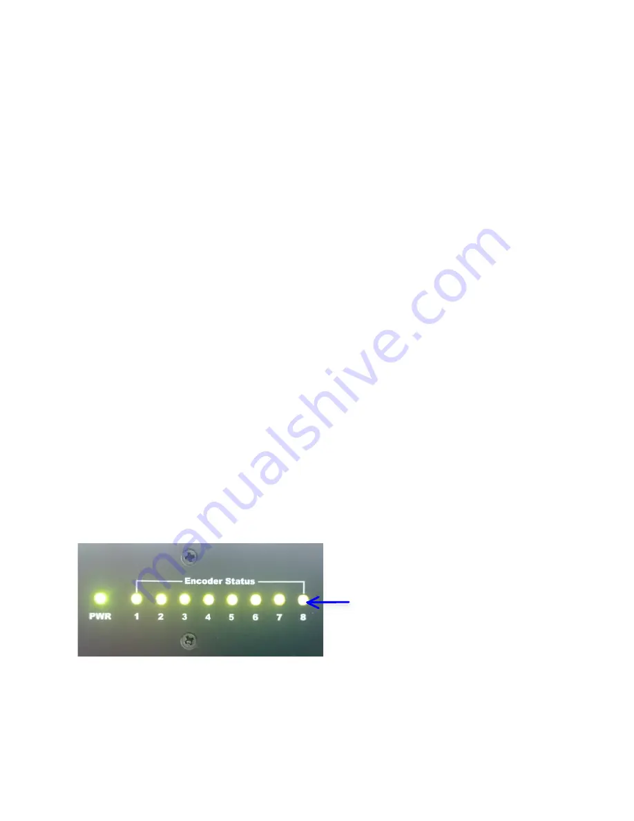
Encoder Status Lights

:


Solid Green

 Encoder connected to Input source


Flashing Green:

 No connection / free run


Flashing Red:

 EAS Event  

Summary of Contents for HDME-804

Page 1: ...HDME 804 Manual V1 0 1 16 1 User Guide and Installation Manual HDME 804 Eight Input QAM Encoder Modulator MPEG 2 H 264 HD ENCODER with QAM IP ASI Outputs...

Page 2: ...ns and Connections 6 Connecting to the GUI Interface 7 Encoder Programming and Setup via GUI Interface 7 Overview Page of HDME 804 8 GUI Login Password 8 Common Setup 9 VCN Modes Available 10 RF Setup...

Page 3: ...and invalidate the manufacturer s warranty DO NOT connect the power cord to the device if the power cord is damaged DO NOT cut the power cord DO NOT plug the power cord into an AC outlet until all cab...

Page 4: ...of DTV standards The Dolby Digital Encoding capabilities rounds out this feature rich product This space saving design delivers up to 8 High Quality HD SD QAM IP ASI channels in a single 1RU space Dol...

Page 5: ...presets Channel Type STD HRC IRC VCN VCN Auto VCN Manual VCN 1 Part Attenuation 1 20dB 1 db Steps RF Output F Female 75 Closed Captioning Control Supported IP Output Type 1RJ 45 GbE Stream Type UDP R...

Page 6: ...d Composite video inputs The HDME 804 encoder modulator is intelligently designed to detect the video input from the video source HDMI Connection Connect the HDMI cable s from the video source s into...

Page 7: ...Ethernet Cable to your PC Laptop 2 Modify your PC Laptop IP address to 192 168 1 11 3 Enter 192 168 1 9 into your web browser 4 Enter GUI and make required device changes 5 Save all changes as require...

Page 8: ...RF Output 2 RF Output 3 RF Output 4 by selecting the RF Output tab of the device you want to monitor Step 2 Login Select Common Setup Once the Common Setup Tab is selected you will be prompted to ente...

Page 9: ...eing installed in the system If outputting directly into a HDTV you must first attenuate the output 45dBmV typical Notes on Changes Changes made to an individual setup tab may require the installer to...

Page 10: ...manually Although the Output Channel is set to 102 663 0000MHz the Major Minor Channels do not have to follow or correspond to the output channel Example Output Channel 102 5 1 5 2 QAM 1 6 1 6 2 QAM...

Page 11: ...channel 2 RF QAM channel 3 and RF QAM channel 4 Go to Encoder Page to Set Modify the VCN Channel if VCN Manual or VCN One Part selected Notes on Channel Selection The image below shows the Output Chan...

Page 12: ...RF Output Select RF Output 1 RF Output 2 RF Output 3 or RF Output 4 Select and set the required parameters you require for your installation The HDME 804 offers the integrator the ability to disable...

Page 13: ...14 15 16 Step 7 Encoder Setup Encoder Setup Select Encoder 1 2 3 4 8 tabs to program any individual encoder Select and change all desired parameters VCN Channels can be set if VCN Mode was set to Majo...

Page 14: ...method protocol and Destination IP Port and TTL settings Network Setup IP address for IP Output Port Default 192 168 1 10 Streaming Methods Available RTP UDP Unicast and RTP UDP Multicast Disabling IP...

Page 15: ...e encoder s settings are changed and a Local Save was performed for each Setup tab Select Upload and Reboot on the IP Streaming page This function will upload and save all parameters set in the Common...

Page 16: ...d set Host Name Step 13 Save Network Configuration Save Config Once all parameters are set you are required to select Save Config This function will reboot and save the changes setting for the Network...

Page 17: ...be lost Step 15 If required change GUI Password and Submit Note When setting a new password you must use the Submit button This password is for access to the GUI only The LCD front Panel Password wil...

Page 18: ...video from the EAS system device Once the encoder has received the proper signal from your EAS device the normal input video and audio will return to a normal operating mode THIS DEVICE IS NOT AN EAS...

Page 19: ...HDME 804 Manual V1 0 1 16 19 Product Notes Distributed by...

Reviews: