11
1x
Sensor position out of working range
2x
Working range incorrectly set
3x
Off the tolerance level of magnetic field
4x
Wrong parameters in EEPROM
5x
Wrong parameters in RAM
4. Calibration of currents 4 mA and 20 mA.
On switching-on the power supply, keep the push-buttons “4” and “20” depressed and release them after a sin-
gle blink of LED. In this way the option menu 4.1 Calibration of current 4 mA is entered.
4.1. Calibration of current 4 mA
Connect the ammeter to testing terminals. Press the push-button “20”. Keep depressed the push-button to evoke
the auto-repeat of current decrease. Release the push-button to make record of the present value.
4.2. Calibration of current 20 mA
Connect the ammeter to testing terminals. Press the push-button “4”. Keep depressed the push-button to evoke
the auto-repeat of current increase. Release the push-button to make record of the present value.
4.3. Switching-over between option of calibration 4 mA and 20 mA
Entry of option of calibration 4 mA:
Press the push-button “4”, then the push-button “20” and keep them depressed until LED blinks.
Entry of option of calibration 20 mA:
Press the push-button “20”, then the push-button “4” and keep them depressed until LED blinks.
5. Record of standard parameters
On switching-on the power supply, keep the push-buttons “4” and “20” depressed and release them after
a double blink of LED.
ATTENTION! With this record, the transmitter calibration is also overwritten and, therefore, it must be repeated!!
Parameter setting
ACTUATOR ASSEMBLY AND PUTTING INTO OPERATION
After unpacking the actuator, this should be inspected for possible visible signs of damage that could happen
during transportation or storage. If no visible damages are detected, the actuator can be connected to external con-
trol and power circuits. Using a short-time switching-on of the actuator in its intermediate position of the working
stroke, make sure that the actuator output shaft rotates in a correct direction. This can be verified by pressing the le-
ver of the particular micro-switch (end-limit position or torque switch, depending on the way of controlling the actua-
tor) using an insulation rod with the actuator operating in certain direction. By pressing the lever of the torque switch
MZ or end-limit switch PZ with the output shaft rotating in the Close direction, the actuator should stop. With the
output shaft rotating in the Open direction, the levers MO and PO should be pressed. If the actuator does not stop by
the mentioned pressing but does stop by pressing the levers MO and PO with rotation in the Close direction or MZ
and PZ with rotation in the Open direction (i.e. the micro-switch levers switch off the electric motor with rotation in
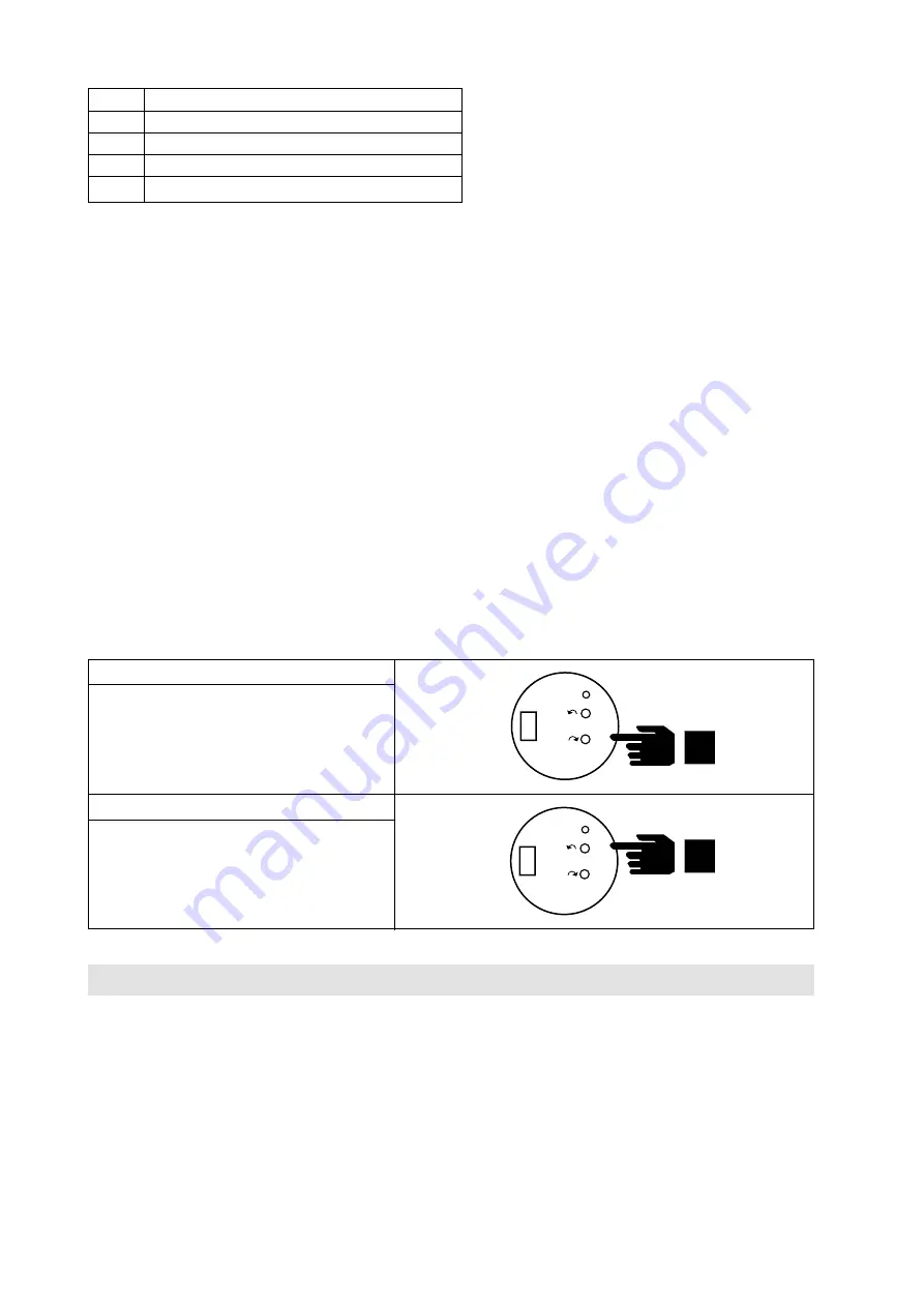
Position “4 mA“
Set the actuator to required position (usually
Closed) and keep the push-button 4 depressed
until LED blinks.
Position “20 mA“
Set the actuator to a required position (usually
Open) and keep the push-button 20 depressed
until LED blinks.
20
4
- L
+ L
- U
+ U
1
DCPT
EHL elektronika
v.č. 000106
20
4
- L
+ L
- U
+ U
1
DCPT
EHL elektronika
v.č. 000106
2 s
2 s


