background image

3

© Copyright 2017 Zoeller

®

 Co. All rights reserved.

Recommended Limits of Application for Progressing Cavity Grinder Pumps

Simplex Station

Duplex Station

Model

HP

Homes

GPD

Homes

GPD

810

1

1

400

2

800

815

2

1

400

2

800

These recommended application limits are for pump stations pumping to a gravity main. Low-pressure collection systems should be designed with 

a pump located at each house. For applications where a lift station would handle more than 2 homes, consider the 840 or 71 Series grinder pump.  

For applications where a lift station would handle more than 60 homes, a solids handling type pump should be considered.

General Information

FIGURE 1.

PROGRESSING CAVITY

GRINDER PUMP DESCRIPTION

1.  Pumps are constructed of class 30 cast iron protected with powder 

coated epoxy for long life when pumping sewage in submersible 

applications.  The cutter assembly is comprised of stainless steel 

components hardened to a value of 55-60 on the Rockwell C scale; 

a star shaped cutter and a precision ground flat disk.  Cutting action 

takes place with the rotation of the cutter blades at 1750 RPM against 

the stationary cutter plate (see page 7).

2.  The cutter mechanism on the model 810 & 815 is single directional.

3.  Pump motors are single phase.  Single phase motors require a run 

capacitor, which is mounted in the the upper cap of the pump (ref. 

page 4).  The units have an internal thermal overload.

4.  The 810 & 815 progressing cavity grinder pumps are single seal.

5.  The pressure relief valve provides motor protection under inadvertent 

shut-off head condition.

6.  A progressing cavity grinder pump is an intermittent duty pump designed 

for pumping sanitary sewage. It is not a dewatering or trash pump.

FIELD ASSEMBLED INSTALLATION

1.  Installation and piping instructions are included with the control panel, rail 

system and basin instructions.  If pump is being retrofitted to an existing 

rail system, accessory parts may be required.  Consult the factory and 

advise make and model of rail system being used.

2.  Refer to the appropriate Indoor/Outdoor prepackaged instructions for more 

information on system installation.

3.  All electrical connections including pump to control box and power supply 

to control panels must comply with the “National Electrical Code” and 

applicable local codes. Conduit and panel enclosure openings must have 

a gas-tight seal. Installation of electrical panels and connections should 

be made by a qualified licensed electrician.

4.  A properly sized disconnect switch, supplied by others, shall be installed 

on the service side of the pump and control panel.

5.  When used in a pressure sewer, install an anti-siphon valve (see Fig. 5A).

018330

0

2

4

6

8

10

12

14

16

0

20

40

60

80

100

120

140

160

180

200

260

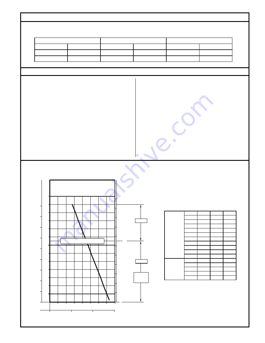
PUMP PERFORMANCE CURVE

MODEL 810/815

8

16

24

32

40

48

56

64

GALLONS
LITERS

METERS

FEET

TOT

AL

 DYNAMIC HEAD

FLOW PER MINUTE

220

240

72

20

40

60

10

20

30

40

50

60

70

80

90

100

110

0

PSIG

TOT

AL

 DYNAMIC HEAD

2 HP

1 HP

LOW PRESSURE SEWER

TYPICAL

OPERATING

RANGE

DESIGN PRESSURE (150 FT OR LESS)

TOTAL DYNAMIC HEAD/FLOW

PER MINUTE

MODEL

Feet

810

Meters

Gal.

Liters

MODEL

815

5

10

20

6.1

3.0

1.5

14.6

55

40
60

18.3

12.2

80

100

30.5

24.4

120

36.6

140
150

45.7

42.7

55
53
50
47
44

41

38
36
34

14.4
14.0
13.2
12.5
11.7
10.9

10.1

9.4
9.0

160

48.8

180

54.9

200

61.0

220

67.1

240

73.2

5.5

33
30
27
24

21

8.6
7.8
7.0
6.3

Summary of Contents for 810 Series

Page 1: ...mited Warranty Checklist and Application 2 3 General Information 3 Pump Wiring Instructions 4 Typical Outdoor Prepackaged System 5 Installation and Operation Instructions 6 Maintenance 7 Service Checklist 8 FM2458 0117 Supersedes 1215 NOTICE TO INSTALLER Instructions must remain with installation Product information presented here reflects conditions at time of publication Consult factory regardin...

Page 2: ...otect you against the possibility of electric shock 2 Make certain the electrical service is within reach of the power supply cord 3 Make sure any panels and branch circuits are equipped with proper size fuses and circuit breakers An independent power circuit is recommended sized according to the National Electrical Code for the current shown on the grinder pump nameplate 4 For your protection alw...

Page 3: ...rogressingcavitygrinderpumpisanintermittentdutypumpdesigned for pumping sanitary sewage It is not a dewatering or trash pump FIELD ASSEMBLED INSTALLATION 1 Installation and piping instructions are included with the control panel rail system and basin instructions If pump is being retrofitted to an existing rail system accessory parts may be required Consult the factory and advise make and model of...

Page 4: ...range below horizontal Ranges are based on testing in nonturbulent conditions Range may vary due to watertemperatureandcordshape As tether length increases so does the variance of the pumping range Tether Length inches 5 10 Pumping Range GPM 9 13 5 min max SK305D SK2651 ALARM FLOAT PUMP CONTROL FLOAT TREE FLOAT 406 mm 16 MIN OFF Electrical Data Amps KVA Code Winding Resistance Line to Line Model B...

Page 5: ...CTRICAL PIPE SK2540 SK2533 6 5 8 143 mm 8 3 8 213 mm 5 1 4 133 mm 4 3 8 111 mm 10 1 2 267 mm DIA 22 3 8 568 mm 4 103 mm FIGURE 5 1 1 4 NPT ANTI SIPHON VALVE 1 1 4 NPT CHECK VALVE DISCONNECT 1 1 4 SHUT OFF VALVE HOME OWNER JWA CURB VALVE BOX CHECK VALVE SHUT OFF VALVE MAIN OPTIONAL LOCATION 1 1 4 NPT ANTI SIPHON VALVE POSITIVE DISPLACEMENT GRINDER PUMP 1 1 4 DISCHARGE LINE FIGURE 5A SK2810 1 25 BAL...

Page 6: ...1 Review the drawing in Fig 4 on page 5 and the actual system to become familiar with the components in the packaged grinder pump system Review where the unit will be installed Determine where the power feed inlet pipe and discharge pipe will be located 2 Remove the unit from packing Prepackaged outdoor systems are preassembled at the Zoeller Company and require a minimum of field assembly work Fl...

Page 7: ...ted and replace disc and retainer screws Torque to 63 67 in lbs Replace cutter with the correct shims Install washer and torque hex head bolt to 71 75 in lbs apply Loctite 262 thread lock sealant or equal to bolt threads prior to insertion Check running clearance with pump in vertical position to remove end play Clearance must be between 0 007 and 0 012 to obtain efficient grinding when pump is pu...

Page 8: ...er in cap assembly check valve not installed or malfunctioning B Motor overheats and trips on overload Incorrect voltage hydraulic rotor or cutter blocked negative head discharge lower than intake of pump Defective off float Pump runs continuously at low water level Low oil level in motor shell Pump running at shut off head check valve not installed or malfunctioning C Pump will not shut off Debri...

Reviews: