XPCI1C00 Motion Control Card User Manual V1.0
2.
Select “installation from disk”.
Page 1: ......
Page 2: ...he ZMC controller software and the introduction and routine of each command please refer to the ZBASIC software manual Information contained in this manual is only for reference Due to improvements in design and functions and other aspects Zmotion Technology reserves the final interpretation Subject to change without notice Pay attention to safety when debugging the machine Please be sure to desig...
Page 3: ...ided into Danger and Caution Failure to operate as required may result in moderate injury minor injury or equipment damage Please keep this guide in a safe place for reading when needed and be sure to hand this manual to the end user Install Danger When the controller is disassembled all external power supplies used by the system should be disconnected before operation otherwise it may cause misop...
Page 4: ...at the insulation distance between cables will not be reduced after the cables are installed on the terminal block Notice Avoid metal shavings and wire ends falling into the hardware circuit board during installation The cable connection should be carried out correctly on the basis of confirming the type of the connected interface It should be confirmed that the cables pressed into the terminals a...
Page 5: ...6 3 3 1 Adapter EXDB37M 37 16 3 3 2 Terminal Definition 17 3 4 Pulse Directional Output 17 3 4 1 Pulse Direction Axis Specification Wiring 18 3 4 2 Basic Usage Method 19 3 5 Encoder Input 21 3 5 1 Encoder Interface Specification Wiring 21 3 5 2 Basic Usage Method 22 3 6 IN Digital Input 24 3 6 1 Digital Input Specification Wiring 24 3 6 2 Position Sensor Signal Distribution 27 3 6 3 Basic Usage Me...
Page 6: ...ogram Installation 35 5 3 Ordinary Network Card Install EtherCAT Bus Protocol 41 Chapter VI Program Applications 46 6 1 ZDevelop Software Usage 46 6 2 PC Upper Computer Program Application 51 Chapter VII Run and Maintain 54 7 1 Regular Inspection and Maintenance 54 7 2 Common Problems 55 ...
Page 7: ...ntrol at most Pulse output mode pulse direction Support encoder position measurement which can be configured as handwheel input mode Mechanical control input signal EL ORG ALM optoelectronic isolation Maximum pulse output frequency of pulse axis is 5MHZ The maximum output current of general digital outputs can reach 300mA which can directly drive some kinds of solenoid valves Support linear interp...
Page 8: ...er Manual V1 0 A variety of program encryption methods to protect the intellectual property rights of customers 1 3 System Frame 1 4 Model Information XPCI is the abbreviation of the PCI motion control card model launched by Zmotion ...
Page 9: ...are Installment Size 155 108mm The card slot interface is designed according to the PCI V3 0 standard 32 bit card and it is backward compatible with the standard PCI V2 3 PCI doesn t support plug in or pull out when in hot so please close the computer before inserting and pulling the card ...
Page 10: ...nstallation Before installation please ensure that the product is powered off Do not disassemble the module otherwise the machine may be damaged Avoid direct sunlight installation In order to facilitate ventilation and controller replacement 2 3cm should be left between the upper and lower parts of the controller and the installation environment and surrounding components Considering the convenien...
Page 11: ...0 Basic Axes 12 Type of Basic Axes Local pulse axes Digital IO There are 49 inputs and 32 outputs with overcurrent protection IO Input Frequency 5kHz IO Output Frequency 8kHz Highest Pulse Frequency 5MHz Motion Buffer of Each Axis 4096 Power Supply Input 24V DC input Dimensions 155 108mm 2 2 Interface Definition Interface Description ...
Page 12: ... control signals and IO control signals which is used with adapter X301 Signal Interface 1 Include 6 11 axis motor control signals and IO control signals which is used with adapter X500 Signal Interface 1 Include 0 3 axis encoder signals which is used with adapter 2 3 Work Environment Item Parameters Work Temperature 20 60 Work relative Humidity 5 95 non condensing Storage Temperature 40 70 not fr...
Page 13: ...to 3 2 2 Terminal Definition Specification Item Description Voltage DC24V 10 10 The current to open 0 5A The current to work 0 4A Anti reverse connection Valid Overcurrent Protection Valid 3 2 X300 X301 Signal Interface X300 and X301 are main interfaces for motion control and IO signal control of XPCI1C00 It is VHDCI socket and it is necessary to connect ACC 1C00 adapter Below shows X300 and X304 ...
Page 14: ... of axis 0 3 DIR0 Directional signal of axis 0 4 DIR0 Directional signal of axis 0 5 PUL1 Pulse signal of axis 1 6 PUL1 Pulse signal of axis 1 7 DIR1 Directional signal of axis 1 8 DIR1 Directional signal of axis 1 9 PUL2 Pulse signal of axis 2 10 PUL2 Pulse signal of axis 2 11 DIR2 Directional signal of axis 2 12 DIR2 Directional signal of axis 2 13 IN37 ORG0 Origin signal of axis 0 ...
Page 15: ...n limit signal of axis 0 23 IN8 EL0 position limit signal of axis 0 24 IN9 EL1 position limit signal of axis 1 25 OUT0 HW0 Comparison output 0 26 OUT1 HW1 Comparison output 1 27 OUT2 PWM0 Low speed PWM0 28 OUT3 PWM1 Low speed PWM1 29 OUT4 General output 4 30 OUT5 General output 5 31 OUT6 General output 6 32 OUT7 General output 7 33 24V 24V power input 34 EGND 24V power ground Pin Name Description ...
Page 16: ...signal of axis 3 54 IN14 EL3 position limit signal of axis 3 55 IN15 EL4 position limit signal of axis 4 56 IN16 EL4 position limit signal of axis 4 57 IN17 EL5 position limit signal of axis 5 58 IN18 EL position limit signal of axis 5 59 OUT8 General output 8 60 OUT9 General output 9 61 OUT10 ERC0 Error clear signal of axis 0 62 OUT11 ERC1 Error clear signal of axis 1 63 OUT12 ERC2 Error clear si...
Page 17: ... no handwheel PWM0 and PWM0 are low speed ports and the maximum output frequency is 10KHz For the special function hardware comparison output HW0 and HW1 need control card license with HW X301 Pin Definition Pin Name Description 1 PUL6 Pulse signal of axis 6 2 PUL6 Pulse signal of axis 6 3 DIR6 Directional signal of axis 6 4 DIR6 Directional signal of axis 6 5 PUL7 Pulse signal of axis 7 6 PUL7 Pu...
Page 18: ...EL7 position limit signal of axis 7 25 OUT16 General output 16 26 OUT17 General output 17 27 OUT18 General output 18 28 OUT19 General output 19 29 OUT20 General output 20 30 OUT21 General output 21 31 OUT22 General output 22 32 OUT23 General output 23 33 24V 24V power input 34 EGND 24V power ground Pin Name Description 35 PUL9 Pulse signal of axis 9 36 PUL9 Pulse signal of axis 9 37 DIR9 Direction...
Page 19: ...position limit signal of axis 9 55 IN33 EL10 position limit signal of axis 10 56 IN34 EL10 position limit signal of axis 10 57 IN35 EL11 position limit signal of axis 11 58 IN36 EL11 position limit signal of axis 11 59 OUT24 General output 24 60 OUT25 General output 25 61 OUT26 ERC6 Error clear signal of axis 6 62 OUT27 ERC7 Error clear signal of axis 7 63 OUT28 ERC8 Error clear signal of axis 8 6...
Page 20: ...put the power supply of the IO port from EGND and 24V 3 3 X500 Signal Interface The X500 interface is the encoder signal interface and the EXDB37M 37 adapter board is used to connect external devices This terminal is optional if you need to use encoder it can be selected Interface Appearance 3 3 1 Adapter EXDB37M 37 EXDB37M 37 is the adapter board of X500 signal and it is connected through adapter...
Page 21: ... of encoder axis 2 7 EZ0 Signal Z of encoder axis 1 27 NC 8 EZ0 Signal Z of encoder axis 1 28 NC 9 NC 29 GND Internal power ground 10 5V 5V power 30 EA3 Phase A of encoder axis 4 11 GND Internal power ground 31 EA3 Phase A of encoder axis 4 12 EA2 Phase A of encoder axis 3 32 EB3 Phase B of encoder axis 4 13 EA2 Phase A of encoder axis 3 33 EB3 Phase B of encoder axis 4 14 EB2 Phase B of encoder a...
Page 22: ... switch to adjust Pulse direction PUL DIR signal voltage range 0 5V Pulse direction PUL DIR signal max frequency 5MHz Isolation Non isolated Wiring Reference Connect driver to controller it needs to correspondingly connect the PUL and DIR terminals one by one Differential or single ended wiring can be used Both methods can be set by adjusting the dial switch on the board For the specific setting m...
Page 23: ... port is connected it is necessary to connect the GND of the internal power supply terminal 1 to the GND of the driver through ACC 1C00 If the drive and the control card use different 24V power supplies connect the external power supply ground EGND terminals 34 and 66 to the drive COM through ACC 1C00 3 4 2 Basic Usage Method 1 Please follow the above wiring instructions to wiring correctly 2 Afte...
Page 24: ... 4 There are many parameters related to pulse axis they can be set and checked through relative instructions please see axis parameter and axis status of ZBasic or see ZDevelop View Axis parameter 5 Control corresponding motion through View Manual ...
Page 25: ...Specification Item Description Encoder type High speed encoder 0 3 Low speed encoder 4 Encoder signal type Differential single ended input signal compatible Single ended input signal Encoder signal voltage range 0 5V 0 24V Encoder signal max frequency 5MHz 5kHz Isolation Non isolated Isolated Wiring Reference Connect driver to controller it needs to connect A B and Z one by one Both differential m...
Page 26: ...ol Card User Manual V1 0 2 Low speed encoder 4 wiring reference Wiring Note For low speed encoder they are input port reuse function 3 5 2 Basic Usage Method 1 Please follow the above wiring instructions to wiring correctly ...
Page 27: ... axis parameters such as ATYPE UNITS SPEED ACCEL etc 4 There are many parameters related to pulse axis they can be set and checked through relative instructions please see axis parameter and axis status of ZBasic or see ZDevelop View Axis parameter 5 Control corresponding motion through View Manual ...
Page 28: ...Hz Voltage level DC24V Current 4 8mA Max leakage current when off 25μA Voltage to open 14 5V Min current 1 8mA Impedance 4 7Ω Isolation optoelectronic isolation The times in the form are typical based on the resistive load and may change when the load circuit changes Wiring Reference 1 specialized input origin switch signal Generally in motion control system one position sensor needs to be used to...
Page 29: ... through XPCI1C00 3 specialized input position limit switch signal In the motion system one position sensor is usually used to set a mechanical limit point to determine the boundary position of the motion and protect the mechanical equipment Each axis of XPCI1C00 has two position limit signal input ports EL and EL EL is positive limit signal EL is negative limit signal The limit switch signal inpu...
Page 30: ...et by software If the limit switch is a normally open switch it is necessary to set the EL signal to be valid at low level When the external mechanical parts touch the limit switch the switch is closed EL is valid and the mechanical parts are prohibited from continuing to move in the original direction If the limit switch is a normally closed switch it is necessary to set the EL signal to be valid...
Page 31: ...01 signal interfaces define dedicated IOs which are used to access signals such as origin limit and alarm The configuration of the sensor can refer to the figure below 3 6 3 Basic Usage Method 1 Please follow the above wiring instructions to wiring correctly 2 After powered on please connect to ZDevelop 3 State values of corresponding input can be read directly through IN command or they can be ch...
Page 32: ...25μA Respond time to conduct 12μs Respond time to close 80μs Overcurrent protection Support Isolation optoelectronic isolation Note The times in the form are typical based on the resistive load and may change when the load circuit changes Due to the leak type output the shutdown of the output will be obviously affected by the external load circuit and the output frequency should not be set too hig...
Page 33: ...rt on the power supply to the negative pole of DC power supply of external input device If the signal area power supply of the external device and the power supply of the controller are in the same power supply system this connection also can be omitted 3 7 2 Basic Usage Method 1 Please follow the above wiring instructions to wiring correctly 2 After powered on please use ETHERNET or RS232 to conn...
Page 34: ...DIP Switch Appearance Usage Description It is one switch to select to set the pulse output mode as differential or single ended output mode Differential position is dialed which means differential output mode is selected Single ended position is dialed which means singled ended output mode is selected Default is differential output mode Note ...
Page 35: ...on of OUT0 OUT31 1 corresponds to initial high level 0 corresponds to initial low level Set Bit 1 of S200 as ON OUT0 OUT9 reverse OUT initial state is 0 IN initial state is 1 the DIP value is 16 Set Bit 2 of S200 as ON OUT10 OUT19 reverse OUT initial state is 0 IN initial state is 1 the DIP value is 32 Set Bit 3 of S200 as ON OUT20 OUT31 reverse OUT initial state is 0 IN initial state is 1 the DIP...
Page 36: ...Standard Accessories Cable The cable is used to connect ACC 1C00 adapter board and signal interfaces X300 X301 and VHDC168 100 length is 1m or VHDC168 200 length is 2m can be selected VHDC168 100 is configured by default VHDCI68 pin male head is fully connected to SCSI68 male head one to one correspondence with shielding Wiring Board Two ACC 1C00 wiring boards are equipped as standard please refer...
Page 37: ...the encoder it supports the expansion of the four axis differential encoder Adapter Cable The 40P socket of the control card can be converted to DB37 through the ZP72 02 conversion cable and can be installed on the card slot of the industrial computer for easy wiring CH2 is connected with X302 Cable ...
Page 38: ...the interface board which is convenient for users to install and connect the interface board 37 pin male to male full contact one to one correspondence shielded The cable length is 1 5 meters Wiring Board Please refer to 3 3 1 EXDB37M 37 wiring board description for specific parameters ...
Page 39: ...ert the motion control card into the slot securely and tighten the fixing screws on the baffle strip 4 Remove a baffle bar adjacent to the slot and fix the adapter board on the slot of the chassis with screws 5 2 Drive Program Installation It is used with the card Method 1 install automatically Use the built in installation wizard software dpinst_amd64 exe in the driver directory to automatically ...
Page 40: ... ZMotionRT64 sys file can be installed Method 2 install manually 1 Open the Device Manager menu and select the PCI device in Other Devices 2 If there are multiple PCI devices right click Properties to view detailed information select Hardware ID for properties and confirm that it is a PCI device starting with PCI VEN_EF34 DEV_1000 ...
Page 41: ...XPCI1C00 Motion Control Card User Manual V1 0 3 Find PCI Device right click to select update drive program ...
Page 42: ...XPCI1C00 Motion Control Card User Manual V1 0 4 Select browse my PC to check drive program 5 Click browse and select driver folder ...
Page 43: ...XPCI1C00 Motion Control Card User Manual V1 0 6 Click next step 7 Wait until installed click close ...
Page 44: ...XPCI1C00 Motion Control Card User Manual V1 0 8 If there is ZMotionRTController in the device manager the installation is successful ...
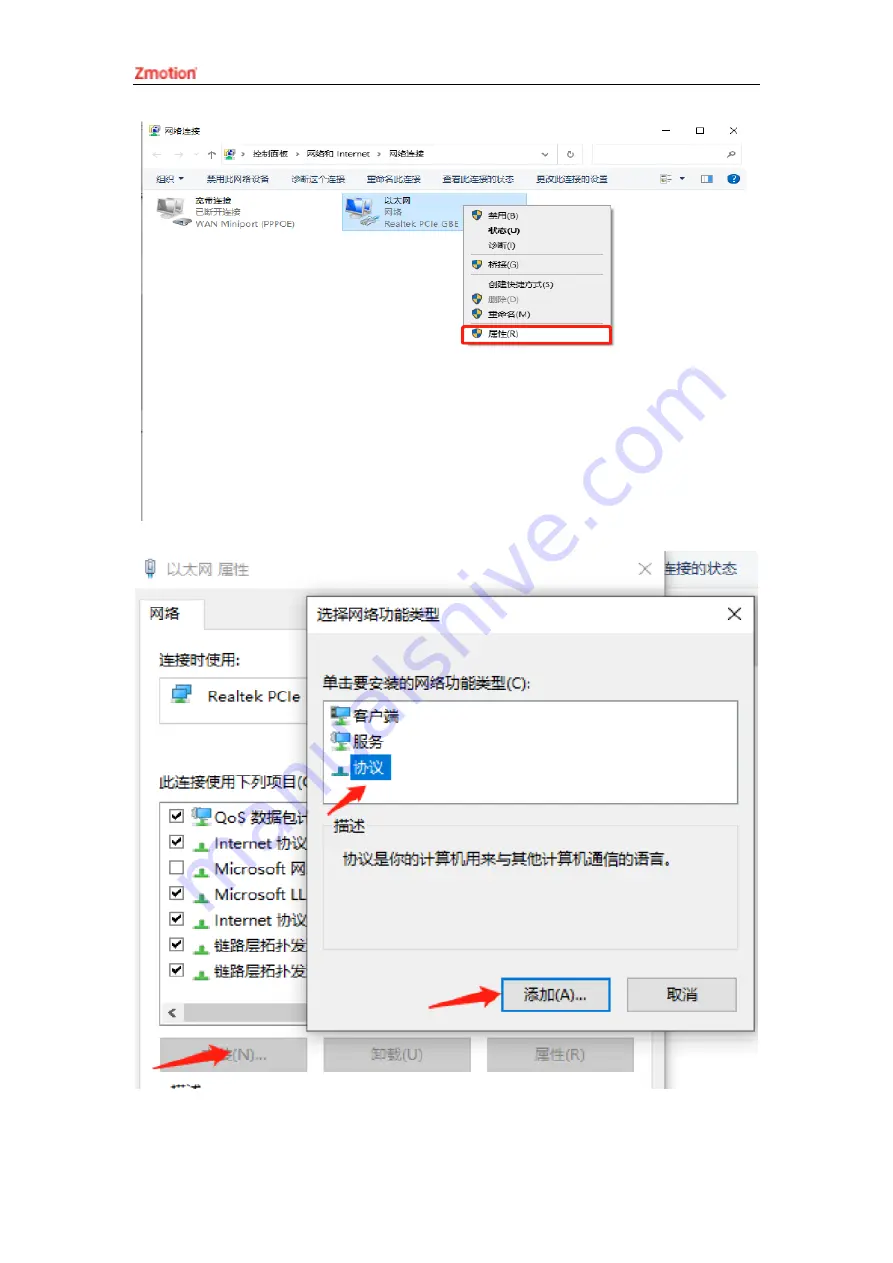
Page 45: ...Bus Protocol MotionRT710 supports the ETHERCAT network port of XPCIE and also supports the common network port of the computer as ETHERCAT 1 On the Windows network connection interface select the network port that needs to be used as the bus right click Properties Installation Protocol Add ...
Page 46: ...XPCI1C00 Motion Control Card User Manual V1 0 2 Select installation from disk ...
Page 47: ...XPCI1C00 Motion Control Card User Manual V1 0 3 Brower drive position select ZMotionRtPacket inf ...
Page 48: ...ftware cannot install this agreement If there is ZMotionRT64PacketProtocolDriver in the properties it means the installation is successful and you can add the corresponding network port bus protocol if you check it The network port that does not connect to the device can be unchecked here ...
Page 49: ...XPCI1C00 Motion Control Card User Manual V1 0 ...
Page 50: ... controller program quickly develop applications diagnose system operating parameters in real time and watch the motion controller The running program is debugged in real time and supports Chinese and English bilingual environments ZBasic ZPLC and ZHMI can run multi tasks and ZBasic can run multi tasks and can be mixed with ZPLC and ZHMI Step Operations Display Interface 1 Open ZDevelop click File...
Page 51: ...XPCI1C00 Motion Control Card User Manual V1 0 2 Click File New File select file type to build here select Basic click OK 3 Double click AutoRun enter task number 0 ...
Page 52: ...t basic file will be saved under zpj project automatically Save all means all files under this project will be saved 5 Click controller connect if no controller select connect to simulator Then connect to controller window will pop up you can select serial port or net port to connect select matched serial port ...
Page 53: ...Rom download RAM download ROM if it is successful there is print indication at the same time program is downloaded into controller and runs automatically RAM it will not save when power off ROM it will save data when power off and when the program is connected to controller again running according to task number ...
Page 54: ...rrent 8 Click View Scope to open oscilloscope Note When opening an project choose to open the zpj file of the project If only the Bas file is opened the program cannot be downloaded to the controller When the project is not created only the Bas file cannot be downloaded to the controller The number 0 in automatic operation represents the task number and the program ...
Page 55: ...ndows linux Mac Android and wince and provides dll libraries in various environments such as vc c vb net and labview as shown in the figure below PC software programming refers to ZMotion PC Function Library Programming Manual The program developed using the PC software cannot be downloaded to the controller and it is connected to the controller through the dll dynamic library The dll library need...
Page 56: ...n basic box click next or finish 4 Find C function library provided by manufacturer Routine is below 64 bit library 5 Copy all DLL related library files under the above path to the newly created project 6 Add a static library and related header files to the project Static library zauxdll lib 1 Right click the header file first and then select Add Existing ...
Page 57: ...ion lib Related header files zauxdll2 h zmotion h Item 2 Add static libraries and related header files in sequence in the pop up window 7 Declare the relevant header files and define the controller connection handle so far the project is newly created ...
Page 58: ...ycle of the motion controller can be appropriately adjusted according to the surrounding environment to make it work within the specified standard environment Check item Check content Inspection standards power supply Check whether the voltage is rated DC 24 V 10 10 surroundings Whether the ambient temperature is within the specified range when installed in the cabinet the temperature inside the c...
Page 59: ...sening Whether the cable is damaged aged cracked The cable must not have any abnormal appearance 7 2 Common Problems Problems Suggestions Motor does not rotate 3 Check whether the ATYPE of the controller is correct 4 Check whether hardware position limit software position limit alarm signal work and whether axis states are normal 5 Check whether motor is enabled successfully 6 Confirm whether puls...
Page 60: ...e IO board POWER led is ON RUN led is OFF 1 Check whether the power of the power supply is sufficient At this time it is best to supply power to the controller alone and restart the controller after adjustment 2 Check whether the ALM light flickers regularly hardware problem RUN led is ON ALM led is ON 1 Program running error please check ZDevelop error code and check application program Fail to c...
Page 61: ... can be checked and captured after connection through serial port 3 When net port led is off please check wiring 4 Check whether controller power led POWER and running indicator led RUN are ON normally 5 Check whether the cable is good quality change one better cable to try again 6 Check whether controller IP conflicts with other devices 7 Check whether controller net port channel ETH are all occu...