background image

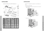
HEIGHT OF THE KITCHEN COUNTERTOP BASED  

ON THE MIN/MAX. HEIGHT OF THE CABIN

A

B

C

Standard

4” (102mm)

32 11/16” (831mm)

84” (2134mm)

Minimum

3 13/16” (97mm)

32 1/2“ (826mm)

83 13/16“ 

(2129mm)

Maximum

5 3/8“ (137mm)

34 1/8“ (866mm)

85 3/8“ (2169mm)

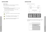
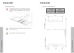
CATEGORY

RBIV30

RBIV36

D

30” (762mm)

-

E

29 3/4” (756mm)

-

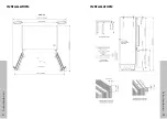
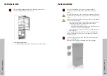
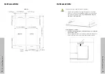
RBIV-36

RBIV-30

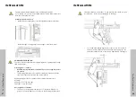
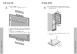
INSTALLATION

INSTALLATION

23

24

Counter

top Height

Pr

oduct Specifications

Summary of Contents for RBIV-30

Page 1: ...BUILT IN REFRIGERATORS www zlinekitchen com Installation Manual...

Page 2: ...d finishes our inspiration is your reality ZLINE is fueled by a passion for innovation A relentless pursuit of bringing the highest end luxury designs and professional features into everyone s homes B...

Page 3: ...ed based on the date of installation The warranty applies only to products installed in the continental United States and the District of Columbia Warranty shall not apply and ZLINE Kitchen and Bath i...

Page 4: ...sions of the installation area must be suitable Dimensions features and position of the object used to support and fix the product to this area must be suitable Minimum clearances between product part...

Page 5: ...center for recycling electrical and electronic equipment Please consult local authorities to learn about the locations of such collection center This installation manual has been prepared to help ins...

Page 6: ...adiators etc The ambient temperature must be between 61 F 16 C and 100 F 38 C Otherwise function errors may arise when the product is running If it is not possible to avoid installing the product near...

Page 7: ...y procedures must be performed by a qualified electrician ATTENTION Do not install your refrigerator In open areas In environments where water is dripping In environments where temperature is lower th...

Page 8: ...IVES FOR INSTALLATION The product can be placed in various ways based on the kitchen design It must be installed at a place where it is ensured that the door can be opened and closed properly If the d...

Page 9: ...ting the installation CATEGORY RBIV 30 RBIV 36 A Width 30 762mm 36 914mm B Depth 25 635mm 25 635mm C Height 84 2134mm 84 2134mm LOCATION OF THE ELECTRICAL WIRING Location of the electrical wiring must...

Page 10: ...ater pressure to exceed 120 psi Make sure that there is no water leakage when making the water connections Otherwise there will be water on the floor and the cabinets will get damaged You will need a...

Page 11: ...PRODUCT DIMENSION RBIV 30 RBIV 36 15 Product Specifications 16 Product Specifications INSTALLATION INSTALLATION...

Page 12: ...CATEGORY RBIV 30 RBIV 36 A 15 1 4 388mm 15 1 4 388mm RBIV 30 INSTALLATION INSTALLATION 17 18 Product Specifications Product Specifications...

Page 13: ...RBIV 30 RBIV 36 INSTALLATION INSTALLATION 19 20 Product Specifications Product Specifications...

Page 14: ...RBIV 36 INSTALLATION INSTALLATION 21 22 Product Specifications Product Specifications...

Page 15: ...Standard 4 102mm 32 1 1 16 831mm 84 2134mm Minimum 3 13 16 97mm 32 1 2 826mm 83 13 16 2129mm Maximum 5 3 8 137mm 34 1 8 866mm 85 3 8 2169mm CATEGORY RBIV 30 RBIV 36 D 30 762mm E 29 3 4 756mm RBIV 36 R...

Page 16: ...with a Box Cutter through the section illustrated in dotted lines and remove it WARNING REMOVE ALL THE POLYSTYRENE PACKAGING MATERIAL ATTENTION Do not remove the tape of the upper door on the product...

Page 17: ...door top abs 1 1 REMOVE MOUNTING PARTS FROM THE FREEZER COMPARTMENT No PART NAME SPEC RBIV 30 RBIV 36 6 Template door panel paper 1 1 7 Anti tip bracket T4 0 Zn coating 2 2 8 Anchor 8 8 9 Screw anti...

Page 18: ...ST M4x14 8 4 23 Screw door panel hanger bracket ST M4x14 30 34 24 Screw freezer door panel top ST M4 8x16 3 25 Bracket freezer door panel top T1 0 sus 3 26 Screw freezer door panel top M4 12 18 We rec...

Page 19: ...oor pull it forward while freeing it from the rear rail lock tabs to remove it HOW TO REMOVE THE LOWER VENT PANEL Remove the 2 screws to take out the Lower Vent Panel Assembly OW TO REMOVE THE UPPER V...

Page 20: ...nstalled to prevent the appliance from tipping over WARNING Make sure that there is no electrical or water connection where the screws will be tighten and connections will be established WARNING Pleas...

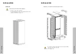
Page 21: ...y you must use the alternative method below In this method you can use wooden blocks to avoid the risk of tipping over It must be installed as illustrated in the figure below There must be no clearanc...

Page 22: ...water hose and power supply on the back Method B Locate the water hose and power supply on the back CABINET INSTALLATION Taking the Refrigerator from the Wooden Pallet Remove the brackets that connec...

Page 23: ...NSTALLATION Screwing the side brackets Fix the brackets Item No17 to the unit where 2 on the top and 3 on every side Use the screws Item No18 to tighten After the product is in the cabinet and leveled...

Page 24: ...are not jammed when moving the refrigerator Push the product carefully towards the cabinet to place it If there is strain during the placement of the product into the cabiniet The floor might be rough...

Page 25: ...el in both width and depth directions You may readjust as needed after panels are installed The maximum height that the adjustable feet can reach is 1 9 16 40 mm and the product height is 85 3 8 2 169...

Page 26: ...door It can adjust the level for 4 different door thickness levels INFO INSTALLATION i You can move the lower vent panel forward backward to adjust it to the kick plate in the kitchen INFO i Once the...

Page 27: ...decorative side of the panel fix the other side of the screw in place with a washer and nut Maximum weights of the door panels to be mounted to the product are as follows Fridge Door 35 7 lbs 16 2 kg...

Page 28: ...ould not be confused with the lower cover Remove two screws to take out the cover door hanger bracket WARNING INSTALLATION Removing the Panel Adjustment Mechanisms on the Refrigerator Remove the upper...

Page 29: ...panels When marking you can use the Door panel preparation template Item No 6 provided with the product INFO Handle connection holes must be adjusted according to the handles to be used in kitchen des...

Page 30: ...these parts It is recommended to keep this template for future reference Attaching the door handles Handle mounting studs need to be installed prior to mounting the panel to the product The mounting...

Page 31: ...EEZER DOOR PANEL RBIV 36 Handle connection holes must be adjusted according to the handles to be used in kitchen design WARNING Minimum thickness of the door must be 19 mm WARNING INSTALLATION INSTALL...

Page 32: ...r handle must not protrude WARNING Lay down the door panel and place the freezer door onto it Put the screws back but do not tighten Use the 3 screws Item No13 to fix the bracket the washers Item No12...

Page 33: ...idge door Use the two screws removed from here to fix onto the adjusting bolts WARNING Adjust from lower part of the door with 2 screws removed from here together with 2 slotted screws Use the bracket...

Page 34: ...ther with 2 slotted screws Use the bracket Item No2 to join the door panel and fridge door use 2 screws Item No20 and 1 screw Item No22 to fix WARNING Clip the decoration cover Item No19 WARNING INSTA...

Page 35: ...y be required should the need to reverse the opening orientation of the door at a later date WARNING INSTALLING THE FREEZER DOOR PANEL Install the freezer door panel assembly onto the rails noting the...

Page 36: ...the door panel 2 Engage set screw1 see the graphic to shift the panel side to side 3 Engage set screw2 see the graphic to shift the panel forward backward engage bolt to set the panel top part in pla...

Page 37: ...engage fixing screw to set the panel in place 4 Engage set screw2 see the graphic to shift the panel forward backward engage bolt to set the panel in place 5 Engage the double threaded bolts fixing th...

Page 38: ...l to adjust the hardness of the upper and lower hinges of the refrigerator door Set the hinge adjustment screw to position I from position O WARNING CHANGING THE DIRECTION OF THE REFRIGERATOR DOOR How...

Page 39: ...2 screws of the upper cover of the fridge door and remove it Remove the upper adjustment kits ATTENTION Loosen 2 screws of the lower cover of the fridge door and remove it Remove lower and upper brac...

Page 40: ...e door panel and lay it down on a table upside down You must attach the door panel by rotating it 180 based on its current position Removing and preparing the fridge inner door Remove the hinge connec...

Page 41: ...aps located at the other side where you will fix the hinges INSTALLATION ATTENTION Remove the lower right hinge by loosening its 2 screws and fix it to its slot at the upper left side INSTALLATION 75...

Page 42: ...osening its 2 screws and fix it to its slot at the lower left side INSTALLATION ATTENTION Attach the hinge slot caps removed from the left side to the hinge caps at the right side INSTALLATION 77 78 D...

Page 43: ...OR Place the fridge inner door to the refrigerator and fix it with 4 screws INSTALLATION Need to purchase a part or accessory for your ZLINE product Visit ZLINEparts com ZLINE s official parts distrib...

Page 44: ...zlinekitchen com 1 614 777 5004 contact zlinekitchen com 2 0 0...

Reviews: