background image

BGM1000 Series Barrier Gate (APP Version)                                                                                                                        User Manual 

P a g e

 | 10 

        Copyright©2023 ZKTECO CO., LTD.  All rights reserved. 


Boom Arm Installation 

5.3

5.3.1


Boom Arm Installation Procedure 

1.


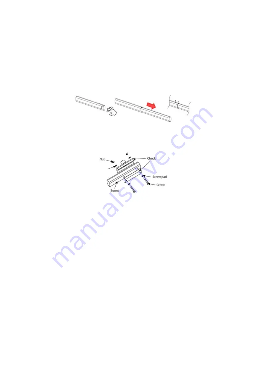
Separate the secondary boom arm from the upper boom arm and fasten it with two 
screws., as shown in Figure 1. 

2.


The procedure of installing the boom arm to the chassis is shown in Figure 2. 


Note: 

1)


Before the barrier is powered on to run the test process, be sure to install the barrier 
boom  arm  of the corresponding length for the test. If the barrier boom arm  is not 
installed, please adjust and remove the spring under the guidance of a professional. 

2)


If the length of the barrier boom arm is cut and adjusted, the tightness of the spring 
and the position of the hanging hole need to be adjusted accordingly to avoid the 
abnormal working status that cannot drop the boom. 


Figure 1 Connect the main boom arm with the Secondary arm together by 2 screws 

Figure 2 Install the Boom Arm to the Chassis 

Summary of Contents for BGM1000 Series

Page 1: ...ad the instructions carefully before operation Follow these instructions to ensure that the product is functioning properly The images shown in this manual are for illustrative purposes only For furth...

Page 2: ...f the said equipment It is an essential pre requisite for the satisfactory operation and maintenance that the operating and maintenance personnel are fully familiar with the design and that the said p...

Page 3: ...letters notes etc for better operation and safety of the machine unit equipment The said additions or amendments are meant for improvement better operations of the machine unit equipment and such amen...

Page 4: ...ndent research and development of biometric verification procedures and the productization of biometric verification SDK which was initially widely applied in PC security and identity authentication f...

Page 5: ...onvention Description Button or key names for devices For example press OK Window names menu items data table and field names are inside square brackets For example pop up the New User window Multi le...

Page 6: ...D 12 7 1 CONNECTION WITH LPR CAMERA 12 7 2 CONNECTION WITH UHF CONTROLLER 13 7 3 CONNECTION WITH LOOP DETECTOR 13 7 4 CONNECTION WITH VR10 RADAR SENSOR 14 7 5 CONNECTION WITH INFRARED PHOTOCELL DETECT...

Page 7: ...P a g e 6 Copyright 2023 ZKTECO CO LTD All rights reserved DIRECTION INTERCHANGE OF THE BOOM ARM 27 9 3 SPRING ADJUSTMENT 28 9 4 10 PRODUCT PACKING LIST 28 11 TROUBLESHOOTING 29 12 SAFETY PRECAUTIONS...

Page 8: ...ures and Functionalities The operating speed is 1 5s and the speed can be adjusted according to different boom arm lengths Reversible left and right directions The transmission mechanism is simple com...

Page 9: ...rating Speed 1 5s 2 5s 5s 2 5s 2 5s Boom Arm Length 3m 4 5m 6m 4 5m 4 5m Boom Arm Type Straight boom Telescopic boom Straight boom with LED Folding boom Chassis Dimension W L H 350 300 1020 mm Motor T...

Page 10: ...the boom arm but it cannot be increased After the boom arm has been cut it is important to set the spring balance again to achieve a new balance The bottom of the spring contains two plastic nuts desi...

Page 11: ...arrier is powered on to run the test process be sure to install the barrier boom arm of the corresponding length for the test If the barrier boom arm is not installed please adjust and remove the spri...

Page 12: ...6 Left and Right Directions 7 Mainboard Wiring Instructions 1 Please disconnect the power supply before wiring 2 To Please note that to change the input voltage you must set the DIP switch to 110V as...

Page 13: ...ier Gate APP Version User Manual P a g e 12 Copyright 2023 ZKTECO CO LTD All rights reserved Wire Connection of the New Mainboard 7 1 Wiring diagram of new control board of the app version Connection...

Page 14: ...13 Copyright 2023 ZKTECO CO LTD All rights reserved Connection with UHF Controller 7 3 Note The Reader1 and 2 of Inbio260 Controller corresponds to LOCK1 Reader3 and 4 corresponds to LOCK2 Connection...

Page 15: ...CO LTD All rights reserved Coil Circumference Coil Number 3m Based on requirements ensure that the inductance is between 100 H and 200 H 3m to 6m 5 to 6 turns 6m to 10m 4 to 5 turns 10m to 25m 3 turns...

Page 16: ...Series Barrier Gate APP Version User Manual P a g e 15 Copyright 2023 ZKTECO CO LTD All rights reserved Connection with Infrared Photocell Detector 7 6 Anti smash function Anti smash and Auto close f...

Page 17: ...he ZKbarrier APP It Supports both Android and iOS systems Operation details are as follows 1 Open the ZKBarrier APP click Wi Fi Connection and then enter the connection page 2 You can choose either Ma...

Page 18: ...n User Manual P a g e 17 Copyright 2023 ZKTECO CO LTD All rights reserved 3 After successful connection you can implement some functions and parameter settings on the APP according to the actual insta...

Page 19: ...first power on you must use the Open and Close buttons on the mainboard to complete the self check process and learn the description of the menu Mainboard Parameter Settings 8 1 Menu Save Menu option...

Page 20: ...Information 01E000 02EXXX Boom Arm Opening Speed Set the Boom Arm Opening Speed to open the gate The larger the number is set the faster the speed The Boom Arm Opening Speed value can be set between 1...

Page 21: ...he bounce sensitivity of the boom arm when it encounters an obstacle The higher the value the lower the sensitivity the longer it will take to bounce When set to 100 this function will be turned off a...

Page 22: ...ch pass in turn 12E000 13EXXX Core Component Position 13E000 Right 13E001 Left 13E001 14EXXX Reset 14E000 Normal 14E001 Reset Select 14E001 will restore the default factory setting Note The function d...

Page 23: ...the valid value is 0 to 251 17E000 18EXXX Core Component Type 18E000 20A to 0 6S 18E001 18B to 1 2S 18E002 18B to 2 5S Please set the parameters according to the core component 18E002 19EXXX Boom Arm...

Page 24: ...ht breathing 22E000 23EXXX Open Close LED State 23E000 The red light flashes during the whole process of opening and closing the boom arm 23E001 The red light is always on during the whole process of...

Page 25: ...exit the menu 8 4 2 Unpairing Long press Menu save then press Stop flip down to 15EXXX Press to set the parameter value and then set the parameter value to 15E200 Press Menu save to save the setting...

Page 26: ...factory Please do not adjust them without the guidance of professionals to avoid mechanical damage 1 Adjust the horizontal position of the boom arm The connecting boom crank will be an overlapping str...

Page 27: ...e connecting boom arm crank is in an unfolded shape and the connecting boom arm s two rotation points and the reducer s output shaft are in an unfolded 3 point line This is the boom arm s vertical pos...

Page 28: ...the power Remove the spring spring hanging arm and boom 2 Change the direction of the Spindle Connecting Arm and linkage Arm 3 Turn the Limited Block to the other direction 4 After the mechanical ope...

Page 29: ...ly Note 1 When the barrier boom is at 45 it is the best balance 2 The spring wire diameter is adapted to different boom lengths 3m boom with 4 5mm 4 5m boom with 5 5mm 6m boom with 6 5mm If the boom i...

Page 30: ...Tighten the wiring Description The power indicator is on the landing boom indicator is normal and the motor is not running Cause 1 The motor wiring might be wrongly connected or the wiring is loose 2...

Page 31: ...the power immediately Note If the product works abnormally please contact the dealer in time Please do not try to repair it by yourself If you handle it without authorization the company is not respo...

Page 32: ...ZKTeco Industrial Park No 32 Industrial Road Tangxia Town Dongguan China Phone 86 769 82109991 Fax 86 755 89602394 www zkteco com Copyright 2023 ZKTECO CO LTD All Rights Reserved...

Reviews: