


MS-SOUND-decoders MS440 to MS990 Page 23
0
10
20
30
40
50
60
70
80
90
100
110
120
130
140
150
160
170
180
190
200
210
220
230
240
250
0 1 2 3 4 5 6 7 8 9
10 11 12 13 14 15 16 17 18 19
20 21 22 23 24 25 26 27 28
0 9 18 27 36 45 54 63 72 81 90 99 108 117 1
26
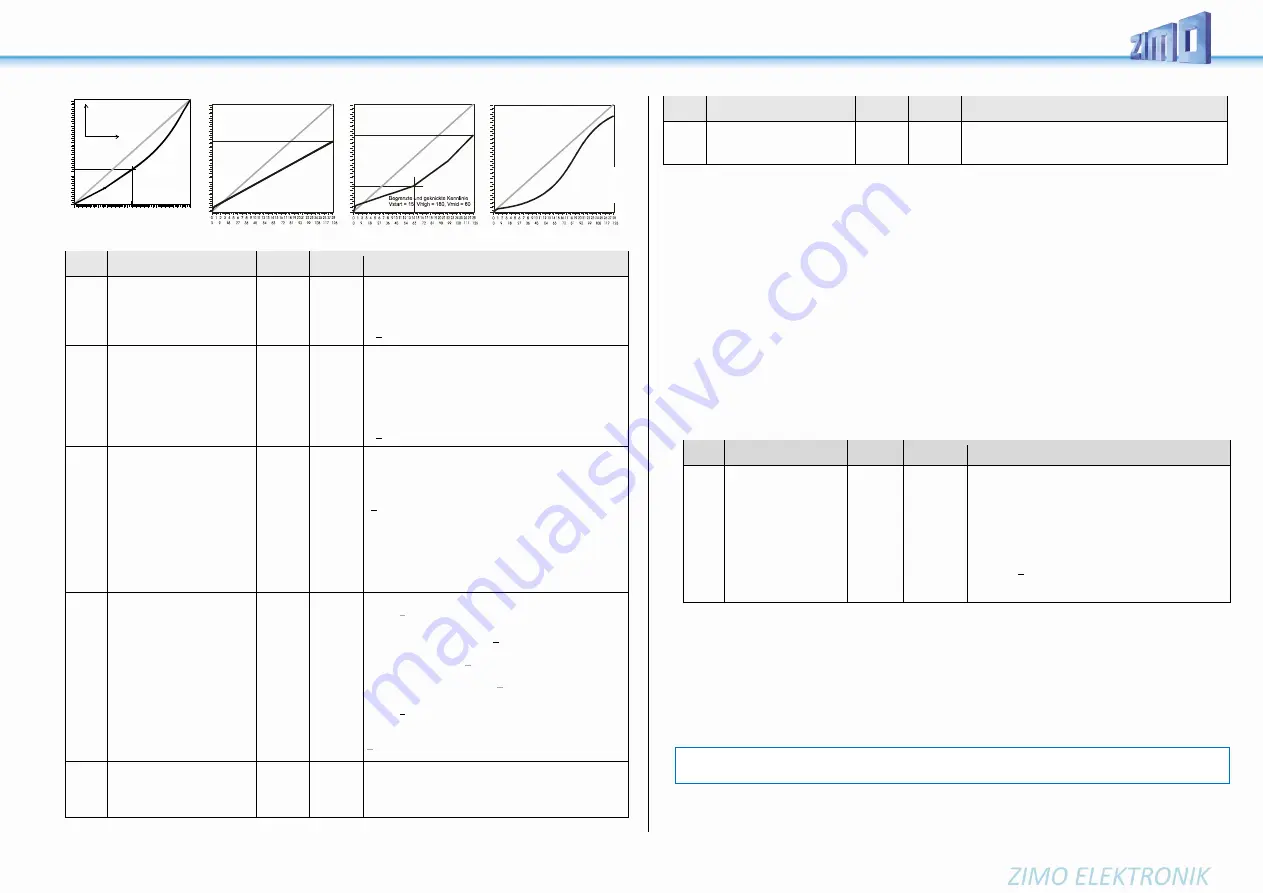
Lin
ea
re
Ke
nn
linie
-
Vs
tar
t=1
, V
hig
h=
25
2,
Vm
id=
12
7
Leicht
geknickte Kennlinie
(Default-Kennlinie)
Vmid = 1 (entspricht 85)
Vstart = 2
Vhigh = 1
(entspricht 252)
in
te
rn
e
Fa
hr
st
uf
e
externe Fahrstufe
Mitte
CV
Denomination
Range Default Description
#2
Start Voltage
Vstart
with 3-point table if
CV #29, bit 4 = 0
1 - 255
1
Internal speed step (1 - 255)
applied as
lowest
external speed step (= speed step 1)
(applies to 14, 28, or 128 speed step modes)
= 1: lowest possible speed
#5
Top Speed
Vhigh
with 3-step curve if
CV #29, bit 4 = 0
0 - 255
1
equals 255
Internal speed step (1 - 255)
applied as
highest
external speed step
(i.e. for the external speed step 14, 28 or 128, depend-
ing on the speed step mode according to CV #29, bit 1
= 0)
= 0: equals 255 as highest speed step
=1: equals 255 as highest speed step
#6
Medium
Speed
Vmid
1 -
¼ to ½
of the
Value in
CV #5
1
(= @ 1/3 of
top speed)
Internal speed step (1 - 255) for
medium
external
speed step (i.e. for the external speed step 7, 14 or 64,
depending on the speed step mode 14, 28 or 128 ac-
cording to CV #29, bit 1)
”1" = default characteristic (medium speed is set to one
third of the top speed. I.e. if
CV #5 = 255: the curve is the same as if CV #6 would
be programmed to 85).
The speed curve resulting from CVs #2, #5 and #6
is automatically smoothed out, therefore no sharp
bends.
#29
Basic configuration
0 - 63
14 =
0000 1110
so bit 4 = 0
(3-point
Speed table)
Bit 0 - Train direction:
0 = normal, 1 = reversed
Bit 1 - Number of speed steps:
0 = 14, 1 = 28/128
Bit 2 - automatic change to analog operation
0 = disabled 1 = enabled
Bit 3 - RailCom („bidirectional communication“)
0 = deactivated
1
= activated
Bit 4 - Individual speed table:
0 = off, CVs #2, #5 and #6 are active.
1 = on, according to CVs #67 – #94
Bit 5 - Decoder address:
0 = primary address as per CV #1
1 = ext. address as per CVs #17 & #18
#67
-
#94
Free (28-point)
speed table
if CV #29, bit 4 = 1
0 - 255
*)
internal speed steps (each 1-255) for each of the 28
external steps.
*) The 28-point default curve is also bent, emphasising
the lower speed range.
CV
Denomination
Range Default Description
#66
#95
Directional speed trimming
0 - 127
0 - 127
0
0
Speed step multiplication by “n/128” (n is the trim value
in this CV): #66: for forward direction; #95: for reverse
direction
CV #57 - Voltage reference for the motor regulation
CV #57
specifies the reference value (voltage) used for motor regulation. For example: if 14 V is se-
lected (CV value: 140) the decoder tries to send the exact fraction of this voltage determined by the
position of the slider to the motor, regardless of the voltage level at the track. As a result, the speed
remains constant even if the track voltage fluctuates, provided the track voltage (more precisely, the
rectified and processed voltage inside the decoder, which is about 2 V lower) doesn’t fall below the ab-
solute reference voltage.
The default value “0” in CV #57 selects the “relative reference”, which automatically adjusts the reference
voltage to the available track voltage. This setting is only useful, if the system can keep the track voltage
constant at all times (stabilized track output) and the resistance along the track kept to a minimum. All
ZIMO systems keep the track voltage stable - even older systems - but not every system from other
manufacturers do, especially relatively cheap systems built before 2005. It is not recommended to set
CV #57 to “0” with systems that don’t keep track voltage stabilized. Instead set this CV to about 2 V be-
low track voltage (i.e. 140 for 16 V).
CV #57 can also be used as an alternative to CV #5 (top speed), which has the advantage that the full
resolution of the 255 speed steps remains available.
CV
Denomination
Range
Default Description
#57
Voltage reference
0,
100 - 255
0
Absolute voltage in tenth of a volt applied to the motor
at full speed (max. throttle setting). A useful (and well
functioning) range is 10 to 24 V (i.e. 100-240), and
lower than the expected track voltage.
EXAMPLE: A system from another manufacturer is set
to 22 V at idle but drops to 16 V under load: A good
setting would be CV #57 = 140 - 150.
CV #57 = 0: automatically adapts to the track voltage
(relative reference); only useful with stabilized track
voltage.
Tweaking the motor regulation by controlling algorithm
The motor’s performance, especially at crawling speeds (as judder-free as possible), can be fine-tuned
with the following parameters:
CV #9 – Motor control frequency and EMF sampling rate
The motor’s PWM is high frequency (typ. 20 kHz, also above the frequencies audible for the human
ear). Compared to the low frequency control (used until the 1990s, usually around 100 Hz)
quiet
and
enginefriendly
.
When using high frequency, the power supply to the motor is interrupted periodically with low frequen-
cies (50 – 200 times/sec.), in order to determine the current speed by measuring back-EMF (voltage
generated by the motor). The more frequent these interruptions happen (sampling rate), the better; but
0
10
20
30
40
50
60
70
80
90
100
110
120
130
140
150
160
170
180
190
200
210
220
230
240
250
Begrenzte lineare Kennlinie
Vstart = 10, Vhigh = 165,
Vmid = 90
0
10
20
30
40
50
60
70
80
90
100
110
120
130
140
150
160
170
180
190
200
210
220
230
240
250
0
10
20
30
40
50
60
70
80
90
100
110
120
130
140
150
160
170
180
190
200
210
220
230
240
250
Beispiel einer frei program-
mierten Geschwindigkeits-
kennlinie (entsprechende
Eintragungen in den Konfi-
gurationsvariablen # 67 - 94)
NOTE
: Frequencies higher than 20 kHz do not have an advantage for motor manufacturers and lead to a (slightly)
higher heat loss within the decoder. Therefore, the option to 40 kHz on the new decoders is not planned anymore.


