16
All information contained herein is the exclusive copyright of Round Bank Engineering Ltd and is not to by copied,
duplicated or otherwise distributed without the express permission of Round Bank Engineering Ltd, Unit 7, Victoria
Business Park, Halifax, UK, HX1 5ND - +44 (0) 1422 647177
–
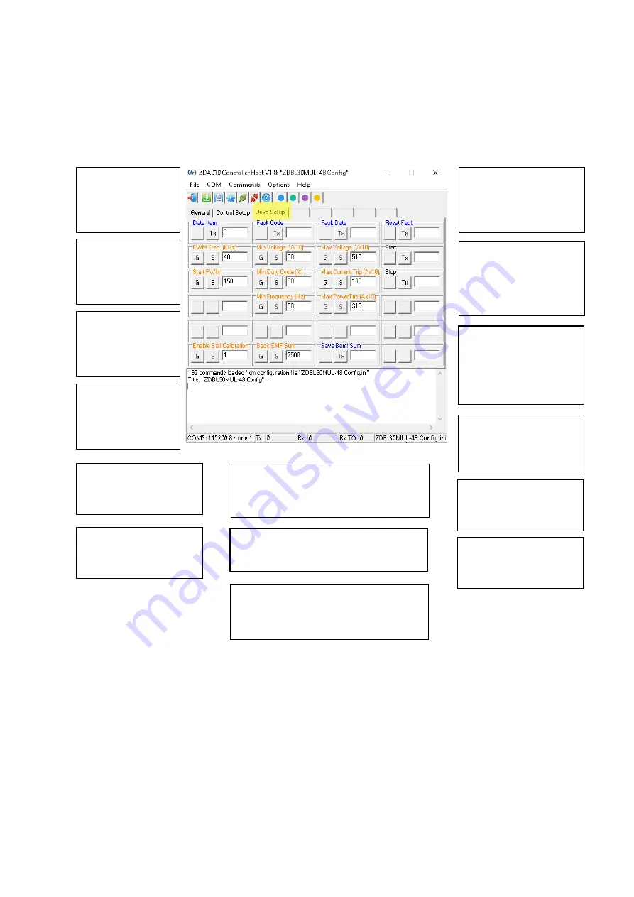
Drive Setup TAB
These are the parameters used for setting up the motor drive.
Data Item
Reads various variables
within the Drive Protect
Module. See below.
Fault Code
Reads the Drive Protect
Fault Code if something
has gone wrong.
Fault Data
Reads the data of the
fault.
Reset Fault
Resets the fault code.
Min Voltage (Vx10)
Minimum supply voltage x 10
before the controller stops
motor and generates fault
code. Ie, 90 = 9.0V.
Max Voltage (Vx10)
Maximum supply voltage x 10
before the controller stops
motor and generates fault
code. Ie, 165 = 16.5V.
Start PWM
PWM Duty Cycle used to Start
the motor.
Min Duty Cycle (%)
Deceleration End Duty Cycle.
PWM Frequency (Khz)
Sets the PWM Frequency to
the motor.
Max Trip Current (Ax10)
Trip Current Setting.
Min Frequency (Hz)
Deceleration End Frequency on
PID.
Max Trip Power
Trip Power Setting.
Back EMF Sum
This is the Self calibration value
Save BEMF Sum
Click this button to save the current BEMF value to
be used on Power up.
Enable Self Calibration
Used to either enable or disable the self-calibration
algorithms.


