E
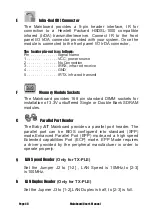
Infra-Red (IR) Connector
The Mainboard provides a 5-pin header interface, IR for
connection to a Hewlett Packard HSDSL-1000 compatible
infrared (IrDA) transmitter/receiver. Connect IR to the front
panel I/O IrDA connector provided with your system. Once the
module is connected to the front panel I/O IrDA connector,
The header pin-out is as follows:
Pin . . . . . . . . . . . . . Signal Name
1 . . . . . . . . . . . . . . . VCC, power source
2 . . . . . . . . . . . . . . . No Connection
3 . . . . . . . . . . . . . . . IRRX, infra-red receive
4 . . . . . . . . . . . . . . . GND
5 . . . . . . . . . . . . . . . IRTX, infra-red transmit
F
Memory Module Sockets
The Mainboard provides 168 pin standard DIMM sockets for
installation of 3.3V unbuffered Single or Double Bank SDRAM
modules.
G
Parallel Port Header
The Baby
AT
Mainboard provides a parallel port header. The
parallel port can be BIOS configured into standard (SPP)
mode,Enhanced Parallel Port (EPP) mode,and a high speed
Extended capabilities Port (ECP) mode. EPP Mode requires
a driver provided by the peripheral manufacturer in order to
operate properly.
g
LAN Speed Header
(Only for TX-PLE)
Set the Jumper J2 to [1-2] , LAN Speed is 10MHz,to [2-3]
is 100MHz.
h
LAN Duplex Header
(Only for TX-PLE)
Set the Jupmer J3 to [1-2],LAN Duplex is half, to [2-3] is full.
Page 40
Mainboard User's Manual
Summary of Contents for TX-PLE
Page 4: ......
Page 9: ...Mainboard User s Manual Page 9 Installation Mainboard Diagram ...
Page 17: ...BIOS Setup ...
Page 37: ...Glossary ...

