background image

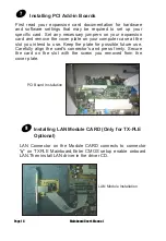
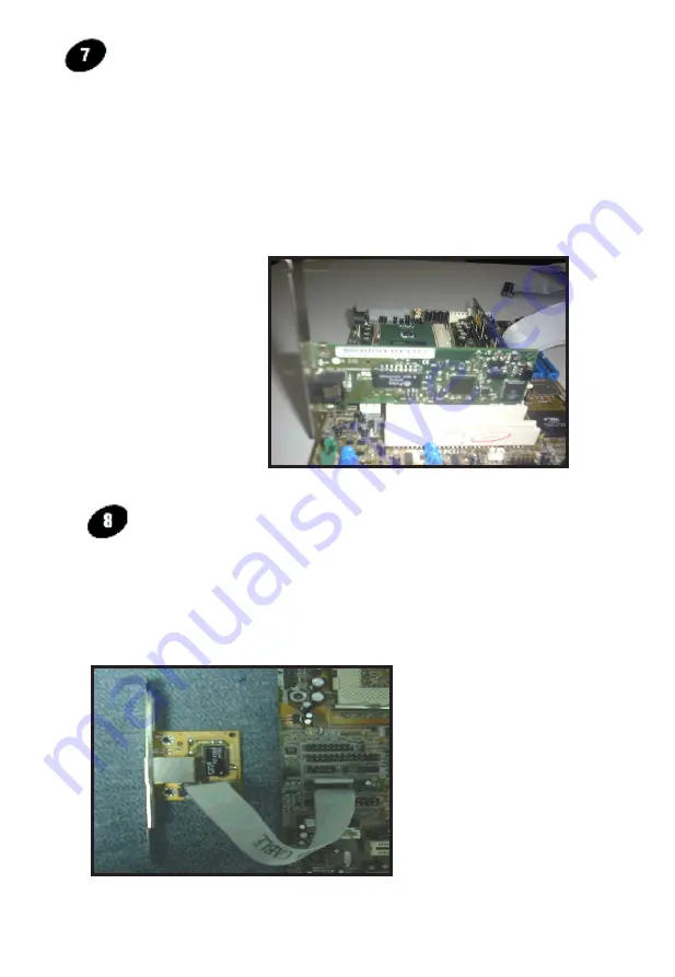
Installing PCI Add-in Boards

PCI Board Installation

First  read  your  expansion  card  documentation  for  hardware 

and  software  settings  that  may  be  required  to  set  up  your 

specific  card.  Set  any  necessary  jumpers  on  your  expansion 

card and remove the cover plate on your computer case at the 

slot  you  intend  to  use.  Keep  the  plate  for  possible  future  use. 

Carefully  align  the  card's  connector's  and  press  firmly.  Secure 

the  card  on  the  slot  with  the  screw  you  removed  from  the 

cover plate.

Page 16

 Mainboard User's Manual

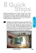
Installing LAN Module CARD (Only for TX-PLE 

Optional)

LAN  Connector  on  the  Module  CARD  connects  to  connector 

"q"  on  TXPLE  Mainboard,Enter  CMOS  setup  enable  onboard 

LAN.Then install LAN driver in the driver CD.

LAN Module Installation

Summary of Contents for TX-PLE

Page 1: ...functional and more competitive Excellent quality and faster response Supporting Intel PENTIUM III FCPGA Celeron FC PGA PPGA Socket 370 Processors UDMA33 66 100 PC133 SDRAM Integrated VGA Graphic Controller Quality Performance Mainboards ...

Page 2: ...el Pentium III Pentium II Celeron are registered trademark of Intel Corporation VIA is a registered trademark of VIA Technologies Incorporated IBM IBM PC IBM PC AT PC DOS OS 2 and OS 2 WARP are registered trademarks of International Business Machines Corporation Ms DOS Windows Windows NT Windows 98 and Windows 95 are registered trademarks of Microsoft Corporation AMI BIOS is a product of American ...

Page 3: ...ng the Memory 12 Attaching the power supply ribbon cable 13 Floppy Disk Drive Connector 14 IDE Connector 14 Mounting Mainboard to chassis 15 Installing Add in Boards 16 Installing LAN Module Card Only For TX PLE Optional 16 BIOS Setup 17 Glossary 32 CD Driver Software Installation Guide 45 Norton AntiVirus OEM Version Setup Guide 46 Mainboard User s Manual Page 3 Table of Contents ...

Page 4: ......

Page 5: ...th 66 100 133MHz Processor Front side Bus Support PC100 PC133 SDRAM DIMM AGP Graphics Controller Integrated inside VIA VT8601A Chipset Dynamic Graphics Memory Allocation on System Memory 64 bit Single Cycle 2D 3D Graphics Engine Supports 2 to 8 Mbytes of Frame Buffer Real Time DVD MPEG 2 and AC 3 Playback Extended Screen Resolutions up to 1600x1200 Extended Text Modes 80 or 132 columns by 25 30 43...

Page 6: ...d circuit assemblies rough edges and corners and hot components Your Location Requirements Are A sturdy level surface for placement Space allowance around mainboard A stable environment with no abrupt temperature or humidity changes No exposure to chemicals or direct sunlight Line voltage and frequency not varying more than or 10 from the value stated on the package or nameplate located on the bac...

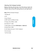
Page 7: ...please contact the representative for part replacement Baby AT Box Standard Package 1 Mainboard 2 CD 3 User Manual 4 IDE Hard Drive Ribbon Cable 5 Floppy Drive Ribbon Cable 6 COM LPT Cable 7 USB Cable for onboard USB Header Optional 8 Audio Game Cable 9 LAN Module Only for TX PLE Optional 10 VGA Cable 11 PS 2 Cable Installation Mainboard User s Manual Page 7 ...

Page 8: ...er Supply Connector 38 b AT Power Supply Connector 39 C Universal Serial Bus USB Header 1 39 c Universal Serail Bus USB Header 2 39 D Serial COM1 Header 39 E Infra Red IR Connector 40 F Memory Module Sockets 40 G Parallel Port Header 40 g LAN Speed Header Only for TX PLE 40 h LAN Duplex Header Only for TX PLE 40 I Lithium Battery 41 J PCI Add in Board Connector 41 M Front Panel Function Connector ...

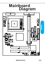
Page 9: ...Mainboard User s Manual Page 9 Installation Mainboard Diagram ...

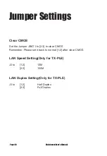
Page 10: ...ear CMOS Remember Please set it back to normal 1 2 after clear CMOS LAN Speed Setting Only for TX PLE J2 to 1 2 10M 2 3 100M LAN Duplex Setting Only for TX PLE J3 to 1 2 Half Duplex 2 3 Full Duplex Page 10 Mainboard User s Manual Jumper Settings ...

Page 11: ...c free before you begin this section The mainboard provides a 370 pins Socket 370 The CPU should have a fan attached to prevent overheating If a fan is not present user should purchase a fan prior to turning on the system The recommended heatsinks for the Socket 370 processor are those with three pin fans that can be connected to the fan connectors on the mainboard It provides the 12 Volts D C for...

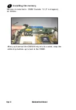
Page 12: ... have set the DIMM firmly into its socket snap the white chip holders up to lock in the DIMM Installing the memory Memory is installed in DIMM Sockets 1 2 F in diagram as follows Page 12 Mainboard User s Manual ...

Page 13: ...from the OS APM must be enabled in the BIOS and OS systems in order for the soft off feature is to work properly Attaching the power supply ribbon cable IMPORTANT Ribbon cables should always be connected with the red stripe on the Pin 1 side of the connector The four corners of the connector s are labeled on the motherboard ATX Power Connector Or AT Power Connector A 12 Pin power supply provides t...

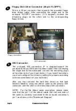
Page 14: ...d connect the remaining plugs at the other end of your hard disk s If you install hard disks you must configure the drives by setting its jumpers according to the documentation of your hard disk Also you may connect the hard disk drives so that both become Masters using one ribbon cable on the primary IDE connector and the other on the secondary IDE connector NOTE For the flat ribbon cable connect...

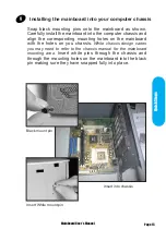
Page 15: ... on the mainboard with the holes on you chassis While chassis design varies you may need to refer to the chassis manual for the mainboard mounting area Insert white pins through the chassis and through the mounting holes on the mainboard into the black pin making sure they have snapped fully into place Black mount pin Insert into chassis Insert White mount pin Mainboard User s Manual Page 15 Quick...

Page 16: ...uter case at the slot you intend to use Keep the plate for possible future use Carefully align the card s connector s and press firmly Secure the card on the slot with the screw you removed from the cover plate Page 16 Mainboard User s Manual Installing LAN Module CARD Only for TX PLE Optional LAN Connector on the Module CARD connects to connector q on TXPLE Mainboard Enter CMOS setup enable onboa...

Page 17: ...BIOS Setup ...

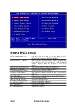
Page 18: ...ard is installed Sets Typematic Rate and Delay Above 1 MB Memory Test Memory Test Tick Sound Hit Del Message Display System Boot Up Sequence and many others Sets chipset specific options and features Controls I O Controller related options Controls power savings options Sets options related to PCI bus and Plug and Play options Display CPU or System Temperature Fan Speed Load Fail Safe Defaults Loa...

Page 19: ...Time Primary Master Primary Slave Secondary Master Secondary Slave Select these options to configure the drive named in the option The BIOS automatically configure the drive A screen with a list of drive parameters appears Floppy Drive A and B Move the cursor to these fields and select the floppy type The settings are 360 KB 5 25 inch 1 2 MB 5 25 inch 720 KB 3 5 inch 1 44MB 3 5 inch or 2 88 MB 3 5...

Page 20: ...y be detected All errors When ever the BIOS detects a non fatal error the system will be stopped and you will be prompted All But Keyboard The system boot will not stop for a keyboard error it will stop for all other errors All But Diskette The system boot will not stop for a disk error it will stop for all other errors All But Disk Key The system boot will not stop for a keyboard or disk error it...

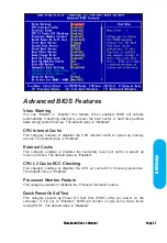
Page 21: ...xternal Cache This category enables or disables the secondary level L2 cache to speed up memory access The default value is Enabled CPU L2 Cache ECC Checking This category enables or disables the CPU L2 cache ECC Checking procedure The default value is Enabled Processor Number Feature This category enables or disables the Processor Number Feature Quick Power On Self Test This category speeds up Po...

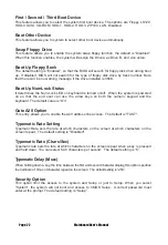
Page 22: ... powered on so that the end user can use the arrow keys on both the numeric keypad and the keyboard The default value is On Gate A20 Option This entry allows you to enable the A20 address line access The default is FAST Typematic Rate Setting Typematic Rate sets the rate at which characters on the screen at which characters on the screen repeat The default setting is Disabled Typematic Rate Chars ...

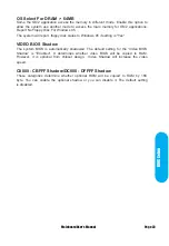
Page 23: ... is Yes VIDEO BIOS Shadow The system BIOS is automatically shadowed The default setting for the Video BIOS Shadow is Enabled It determines whether video BIOS will be copied to RAM However it is optional from chipset design Video Shadow will increase the video speed C8000 CBFFF Shadow DC000 DFFFF Shadow These categories determine whether optional ROM will be copied to RAM by 16K byte You can enable...

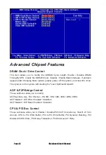
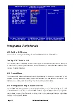
Page 24: ...ystem with loading the Load Optimied Defaults AGP P2P Bridge Control These submenu allow you to modify AGP Aperture size The Choices 4M 8M 16M 32M 64M 128M 256M AGP Master 1 WS Write Enabled Disabled AGP Master 1 WS Read Enabled Disabled CPU PCI Bus Control These submenu allow you to Enable Disable P2C C2P Concurrency Fast R W Turn Around CPU to PCI Write Buffer PCI to PCI Write Buffer PCI Dynamic...

Page 25: ...ows caching of the system BIOS ROM at F0000h FFFFFh resulting in better system performance However if any program writes to this memory area a system error may result The choices Enabled Disabled Video RAM Cacheable Select Enabled allows caching of the video RAM resulting in better system performance However if any program writes to this memory area a system error may result The choices Enabled Di...

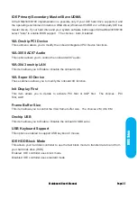
Page 26: ...interfaces supports IDE prefetching for faster drive accesses If you install a primary and or secondary add in IDE interface set this field to Disabled if the interface does not support prefetching The choices Enabled Disabled IDE Primary Secondary Master Slave PIO The four IDE PIO Programmed Input Output fields let you set a PIO mode 0 4 for each of the four IDE devices that the onboard IDE inter...

Page 27: ... VIA 3043 onchip LAN This item allows you to Enable Disable the onboard LAN VIA Super IO Device These submenu allows you to modify the onboard I O function Init Display First This item allows you to decide to activate PCI Slot or AGP first The choices PCI Slot AGP Frame Buffer Size This item allows you to control the VGA frame buffer size The choices 2M 4M 8M Onchip USB This item allows you to Ena...

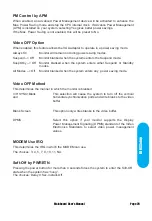
Page 28: ...agement Disables all four modes Min Power Saving Minimum power management Doze Mode 1 hr Standby Mode 1 hr Suspend Mode 1 hr and HDD Power Down 15 min Max Power Saving Maximum power management ONLY AVAILABLE FOR SL CPU S Doze Mode 1 min Standby Mode 1 min Suspend Mode 1 min and HDD Power Down 1 min User Defined Allows you to set each mode individually When not disabled each of the ranges are from ...

Page 29: ...ff Monitor blanked when the system enters any power saving mode Video OFF Method This determines the manner in which the monitor is blanked V H SYNC Blank This selection will cause the system to turn off the vertical and horizontal synchronization ports and write blanks to the video buffer Blank Screen This option only writes blanks to the video buffer DPMS Select this option if your monitor suppo...

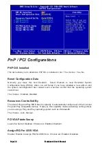
Page 30: ...ct that the operating system cannot boot The choices Enabled Disabled Resources Controlled By The Award Plug and Play BIOS has the capacity to automatically configure all of the boot and Plug and Play compatible devices However this capability means absolutely nothing unless you are using a Plug and Play operating system such as Windows98 The choices Auto Manual PCI VGA Palette Snoop Leave this fi...

Page 31: ...Setup PC Health Status Current CPU Temp Current System Temp Detect CPU and System temperature automatically Corrct FAN1 FAN2 Speed Detect Fan Speed Status automatically 12V 5V Vcore Internal Vcc Detect System Voltages status automatically ...

Page 32: ...Fail safe defaults contain the most appropriate values of the system parameters that allow minimum system performance Load Fail safe Defaults Mainboard User s Manual Page 32 ...

Page 33: ...Load Optimized Defaults Selecting this field loads the factory defaults for BIOS and Chipset Features which the system automatically detects Mainboard User s Manual Page 33 BIOS Setup ...

Page 34: ...nter of the screen to assist you in creating a password Type the password up to eight characters and press Enter The new password will clear the previously entered password from CMOS Memory you will be asked to confirm the Password Type the password again and press Enter Mainboard User s Manual Page 34 ...

Page 35: ...Type Y will quit the Setup Utility and Save the user setup value to RTC CMOS Type N will return to Setup Utility Save Exit Setup Mainboard User s Manual Page 35 BIOS Setup ...

Page 36: ...Type Y will quit the Setup Utility and Without Saving the User setup Value Type N will return to Setup Utility Exit Without Saving Mainboard User s Manual Page 36 ...

Page 37: ...Glossary ...
Page 38: ...te power on off the mainboard can turn off the system power through software control such as the shutdown command in the Windows 95 Start Menu The BIOS system will turn the system power off when it receives the proper APM command from the OS APM must be enabled in the BIOS and OS systems in order to said the soft off feature working properly Pin Signal Name Pin Signal Name 1 3 3V 11 3 3V 2 3 3V 12...

Page 39: ...up b AT Power Supply Connector The Mainboard also provides a 12 pin AT Power supply connector which incorporates standard 5V 12V C Universal Serial Bus USB Header1 The Mainboard provides four 4 pin Universal Serial Bus USB Header USB is a new interface standard for adding external Plug and Play PnP devices to the computer system Peripherals that support USB PnP capabilities can operate at up to a ...

Page 40: ...ets The Mainboard provides 168 pin standard DIMM sockets for installation of 3 3V unbuffered Single or Double Bank SDRAM modules G Parallel Port Header The Baby AT Mainboard provides a parallel port header The parallel port can be BIOS configured into standard SPP mode Enhanced Parallel Port EPP mode and a high speed Extended capabilities Port ECP mode EPP Mode requires a driver provided by the pe...

Page 41: ... Mainboard provides 2 PCI Connectors for the PCI cards M Front Panel Function Connector The Mainboard integrates all system front panel functions into a single on board connector These include connections for the following features Function Connector Pin Out Label System Reset RESET Power LED Keylock PW LED Hard Drive Activity LED HD_ LED Soft Touch Button Power On Off PW BN External Power Saving ...

Page 42: ...system BIOS supports automatic detection of the IDE device data transfer rate and translation between different kinds of device modes such as Logical Block Addressing LBA Extended Cylinder Sector Head ECSH translation modes and ATAPI e g CD ROM devices on both IDE interfaces The two on board IDE connectors support the provided 40 80pin IDE hard disk ribbon cables After connect the single end to th...

Page 43: ...ocket for intel PIII FCPGA Celeron FC PGA PPGA Processor The CPU should have a fan attached to it to prevent overheat If a fan is not present a fan should be installed prior to turning the system on T CPU SYSTEM FAN Connector The recommended heatsinks for the processor are those with 12 Volt three conductor fans that can be connected to the fan connector on the mainboard It provides 12 Volts DC to...

Page 44: ...and the mainboard You may install an auxiliary fan if necessary U Audio Connectors The Mainboard provides Audio headers Audio Connectors S1 Line Output S2 Line Input S3 Microphone Input V VGA Connector The Mainboard provides a VGA Connector for the Integrated Graphics Controller X CD Audio Connector CD Audio input Right Ground Ground Left Y Auxiliary Connector Auxiliary input Right Ground Ground L...

Page 45: ...rating System Windows 95 98 NT 2000 2 Put the CD Disc into the CD ROM Drive and wait for Autorun 3 Select TX PLE TX PLE SE and click your Operating System Type 4 Follow the instruction and install suitable Drivers Page 45 Mainboard User s Manual instant on guide ...

Page 46: ...l Page 46 Norton Anti Virus OEM Version Setup Guide Step 1 Load the Driver CD in CDROM and find the Norton AntiVirus 2001 Install Option Step 2 When CD finishes loading press Install Norton AntiVirus to install the software ...

Page 47: ...Norton Anti Virus Setup Guide Page 47 Mainboard User s Manual Step 3 Follow the installation procedures on screen Step 4 Select Yes and press Finish button to reboot computer ...

Reviews: