

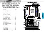
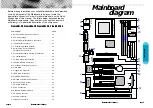
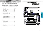
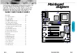


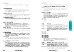
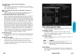
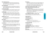

Before we begin installing your series Mainboard we have provided
you with a diagram of the Mainboard to help you locate the
appropriate “connector's” we will make reference to on the Quick
Step portion of this manual. The letters below describes the key
Mainboard components. Page number in the right hand column
will direct you to a detailed description of the component.
CreateBXi-AT, CreateZX-AT, CreateBXv-AT, CreateBX3-AT
COMPONENT
PAGE
a
- AT Keyboard Connector . . . . . . . . . . . . . . . . . . . . . . . .53
b
-
AT Power Supply . . . . . . . . . . . . . . . . . . . . . . . . . . . .53
B- ATX Power Supply . . . . . . . . . . . . . . . . . . . . . . . . . . . .46
e
- Integrated Functional Connector . . . . . . . . . . . . . . . . . .53
F- 3.3v (Memory Module Sockets)
. . . . . . . . . . . . . . . . . .48
G- AT Serial COM1, Serial COM2 and
Parallel Port Cable Connector 's pin headers . . . . . . . .48
H- Accelerated Graphics Port (AGP) Connector . . . . . . . .48
I- 3V Lithium Battery . . . . . . . . . . . . . . . . . . . . . . . . . . . .48
J- PCI Add-in Board Connector's . . . . . . . . . . . . . . . . . . .49
K- ISA Add-in Board Connector's . . . . . . . . . . . . . . . . . . .49
M- Front Panel Function Connector's . . . . . . . . . . . . . . . . .49
N- Flash BIOS . . . . . . . . . . . . . . . . . . . . . . . . . . . . . . . . .50
O- Floppy Drive Connector . . . . . . . . . . . . . . . . . . . . . . . .50
P- IDE Device Connector's . . . . . . . . . . . . . . . . . . . . . . . .50
Q- WAKEUP-LINK Header . . . . . . . . . . . . . . . . . . . . . . . .51
S- CPU Card Slot 1 . . . . . . . . . . . . . . . . . . . . . . . . . . . . .51
T- CPU FAN Connector . . . . . . . . . . . . . . . . . . . . . . . . . .51
U- Audio Connectors . . . . . . . . . . . . . . . . . . . . . . . . . . . . .52
X- CD Audio Connector . . . . . . . . . . . . . . . . . . . . . . . . . .52
Y- Auxiliary Connector . . . . . . . . . . . . . . . . . . . . . . . . . . .52
b
B
a
G
e
F
G
J
I
K
BIOS
M
N
FLOPPY
PRIMARY IDE
SECONDARY IDE
WAKEUP-LINK
IDE2
IDE1
DIMM3
DIMM2
DIMM1
AGP
CPUFAN
P
O
T
PCI1
PCI2
PCI3
PCI4
ISA1
ISA2
CPU SLOT
S
H
Q
COM1
COM2
1
Printer
14
Front Panel JP9
JP2
11
20
10
AUDIO Header
U
SPEAKER
SMI
KEYLOCK
RESET
PWR.ON
IDE..LED
Creative
Sound
Chipset
Y
J25
J24
J23
X
Mainboard
diagram
Page
12
Mainboard User's Manual
Mainboard User's Manual
Page
13


