background image

Mainboard User's Manual

Page 49

J

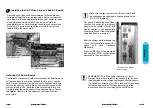
PCI Add-In Board Connector's

K

ISA Add-In Board Connector's

The  Mainboard provides four 32-bit PCI 2 .1 compatible expan-
sion slots and  two 16-bit ISA expansion slots.

M

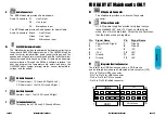
Front Panel Function Connector's

The  Mainboard integrates all system front panel functions into
a single on-board 26-pin connector, JP9. These include con-
nections for the following features:
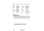
Function

Connector Pin-Out Label

System Reset

RESET

Power LED / Keylock

KEYLOCK

Hard Drive Activity LED

IDE LED

System Speaker

SPEAKER

Soft-Touch Button Power On/Off

SW ON

Turbo LED

TBLED

External Power Saving Control (optional) EXTSMI

KEY

LOCK

KEYLOCK

SPEAKER

EXTSMI

TBLED

RESET

SW ON

IDE LED

13

26

14

GND

GND

VCC

SPKR

PW LED

GND

GND

EXT
SMI

GND

VCC

RST

GND

PUSH ON

GV VR

IDE

LED

ECC

F

3.3V Memory Module Sockets (DIMM)

The  Mainboard provides three 168 pin standard DIMM sockets
for installation of 3.3V unbuffered Single or Double Bank
SDRAM modules. For ZX Series, two DIMM only.

G

Serial COM1, Serial COM2 and Parallel Port Connector's

The 

ATX

Mainboard provides two serial port connector's and

one parallel port connector. Based on the ATX standard, (2) 9-
pin serial ports and (1) 25-pin parallel port are now built on the
mainboard back panel. This design makes your mainboardts
installation easier. The parallel port can be BIOS configured into
standard (SPP) mode, Enhanced Parallel Port (EPP) mode, and
a high speed Extended capabilities Port (ECP) mode. EPP
Mode requires a driver provided by the peripheral manufacturer
in order to operate properly.

The 

AT

Mainboard provides two 10-pin serial ports and one 26-

pin parallel port pin Headers for Cable are now built on the
mainboard.

H

Accelerated Graphics Port (AGP) Connector

The  Mainboard provides an AGP slot compatible with the
Accelerated Grahics Port specification. AGP compliant video
cards offer a much higher throughput than equivalent PCI bus
video cards. PCI currently only supports a 33 Mhz bandwidth,
and can transport at peak rates up to 133 MB/s over its 32 bit
data bus. AGP operates at a 66 Mhz bandwidth which enables 
a peak rate of 266 MB/s in what is known as ‘X1’ mode. Using
‘X2’mode, the peak transport rate can go as high as 532 MB/s.

I

LITHIUM BATTERY

A 3V, CR-2030, Lithium battery is installed on the on-board       
battery socket. This battery is sued to supply the CMOS RAM 
backup power during system powered-off. Danger of explosion 
if battery is incorrectly replaced. Therefore, if you have any dif
ficulties, please consult to the technical personnel.

Page 48

Mainboard User's Manual

Summary of Contents for CreateBX3-AT

Page 1: ...unctional and more competitive Excellent quali ty and faster response Supporting Intel PENTIUM III PENTIUM II or Celeron Processors Accelerated Graphics Port Hardware Monitor Optional Pd Bus Master IDE SDRAM Quality Performance Mainboards ...

Page 2: ...al may or may not be registered trademarks or copyrights of their respective companies and are used only for identification or explanation and to the owners benefit without intent to infringe Intel Pentium Pentium II are registered trademark of Intel Corporation VIA is a registered trademark of VIA Technologies Incorporated IBM IBM PC IBM PC AT PC DOS OS 2 and OS 2 WARP are registered trademarks o...

Page 3: ...CP capable parallel port and support for an IrDA and Consumer Infra Red compatible interface This mainboard is designed to support the new graphic interface standard Accelerated Graphic Port AGP The AGP interface can reach a theoretical 532Mbytes sec transfer rate for 3D graphics data On the other hand the on board 32 bit PCI local bus slots allow a high bandwidth data path which serves as a super...

Page 4: ...components Adhere to warnings regarding accessibility into ares designated only for authorized Technicians Your Location Requirements Are A sturdy level surface for placement Space allowance around mainboard Room temperature 50 to 90 5 F10 to 325 C Relative humidity 20 oc to 80 A stable environment with no abrupt temperature or humidity changes No exposure to chemicals or direct sunlight Line volt...

Page 5: ...nual The letters below describes the key Mainboard components Page number in the right hand column will direct you to a detailed description of the component CreateBXi ATX CreateBXe ATX CreateBXv ATX CreateBX3 ATX COMPONENT PAGE A PS 2 Keyboard Mouse Connector s 46 B ATX Power Supply 46 C Universal Serial Bus USB Connector s 47 E Infra Red IR connector 47 F 3 3v Memory Module Sockets 48 G Serial C...

Page 6: ...or 48 I 3V Lithium Battery 48 J PCI Add in Board Connector s 49 K ISA Add in Board Connector s 49 M Front Panel Function Connector s 49 N Flash BIOS 50 O Floppy Drive Connector 50 P IDE Device Connector s 50 Q WAKEUP LINK Header 51 R SB LINK and Creative PCI Header 51 s Socket 370 CPU Socket 54 T CPU FAN Connector 51 U Audio Connectors 52 W GL520SM Hardware Monitor 52 X CD Audio Connector 52 Y Aux...

Page 7: ... Port Cable Connector s pin headers 48 H Accelerated Graphics Port AGP Connector 48 I 3V Lithium Battery 48 J PCI Add in Board Connector s 49 K ISA Add in Board Connector s 49 M Front Panel Function Connector s 49 N Flash BIOS 50 O Floppy Drive Connector 50 P IDE Device Connector s 50 Q WAKEUP LINK Header 51 S CPU Card Slot 1 51 T CPU FAN Connector 51 U Audio Connectors 52 X CD Audio Connector 52 ...

Page 8: ...e Connector s pin headers 48 H Accelerated Graphics Port AGP Connector 48 I 3V Lithium Battery 48 J PCI Add in Board Connector s 49 K ISA Add in Board Connector s 49 M Front Panel Function Connector s 49 N Flash BIOS 50 O Floppy Drive Connector 50 P IDE Device Connector s 50 Q WAKEUP LINK Header 51 s Socket 370 CPU Socket 54 T CPU FAN Connector 51 U Audio Connectors 52 X CD Audio Connector 52 Y Au...

Page 9: ...refer to the back chapters for further information regarding boot up and configuration An anti static rist band is recommended when handling electronic components be sure your work area is static free before you begin this section The Mainboard provides a 242 pin CPU card slot S in diagram The CPU card should have a fan attached to it to prevent overheating If a fan is not present user should purc...

Page 10: ...hat slot to use for the memory configuration you want The following table for mainboards with WHITE DIMM 3 Only Attaching the power supply ribbon cable IMPORTANT Ribbon cables should always be connected with the red stripe on the Pin 1 side of the connector The four corners of the connector s are labeled on the motherboard Pin 1 is the side closest to the power connector on hard drives and floppy ...

Page 11: ...ves so that both become Masters using one ribbon cable on the primary ID connector and the other on the secondary IDE connector NOTE For the flat ribbon cable connection please make sure that the pin 1 of the ribbon cable the red wire side of the cable is correctly connected to the on board connector s pin 1 as shown on the diagram the mainboard Floppy connection IDE connection Installing the main...

Page 12: ...remove the opening cover plate on your computer case at the slot you intend to use Keep the plate for possible future use Carefully align the card s connector s and press firmly Secure the card on the slot with the screw you removed from the cover plate First read your Video card documentation for hardware and software settings that may be required to set up your specific card Remove the opening c...

Page 13: ...ts Typematic Rate and Delay Above 1 MB Memory Test Memory Test Tick Sound Hit Del Message Display System Boot Up Sequence and many others Sets chipset specific options and features Controls power conservation options Sets options related to PCI bus and Plug and Play options Controls I O Controller related options This option selects the type of CPU install in the motherboard The settings are Auot ...

Page 14: ...a drive with certain identification parameters The number of cylinders in the disk drive The number of heads The actual physical size of a sector gets progressively smaller as the track diameter diminishes Yet each sector must still hold 512 bytes Write precompensation circuitry on the hard disk compensates for the physical difference in sector size by boosting the write current for sec tors on in...

Page 15: ... the computer is powered on This option replaces the old Above 1 MB Memory Test Advanced Setup option The settings are 1st Boot Device This option set the type of device for the first boot drives that the AMIBIOS attempts to boot from after AMIBIOS POST completes The settings are Disabled Network Optical SCSI CDROM IDE 0 IDE 1 IDE 2 or IDE 3 The Optimal and Fail Safe default settings are IDE 0 2nd...

Page 16: ...ry time the system boots or when you run AMIBIOS Setup If Always is chosen a user password prompt appears every time the computer is turned on If setup is chosen the password prompt appears if AMIBIOS is executed See Advanced Setup chapter for instructions on changing a password The Optimal and Fail Safe defaults are Setup Boot To OS 2 Set this option to Enabled if running OS 2 operating system an...

Page 17: ...isabled Older ISA VGA card drivers may not behave correctly if this option is not set to Disabled The Optimal and Fail Safe default settings are Disabled PCI Frame Buffer USWC Set this option to Enabled to enable the USWC memory attribute and improve video performance when a PCI video adapter is installed However VGA card dri vers may not behave correctly when this option is set to Enabled The set...

Page 18: ...in increments of 08h The settings are 00h Fixed Memory Hole This option specifies the location of an area of memory that cannot be addressed on the ISA bus The settings are Disabled 15 MB 16 MB or 512KB 640 KB The Optimal and Fail Safe default settings are Disabled TypeF DMA Buffer Control1 TypeF DMA Buffer Control2 These options specify the DMA channel where TypeF buffer control is implement ed t...

Page 19: ...r Enabled The Optimal and Fail Safe default settings are Disabled Offboard PCI IDE Card This option specifies if an offboard PCI IDE controller adapter card is used in the computer You must also specify the PCI expansion slot on the motherboard where the offboard PCI IDE controller card is installed If an offboard PCI IDE controller is used the motherboard onboard IDE controller is automatically d...

Page 20: ...ecified the IRQ line is used on These options allow you to reserve IRQs for legacy ISA adapter cards These options determine if AMIBIOS should remove an IRQ from the pool of available IRQs passed to devices that are configureable by the system BIOS The available IRQ pool is determined by reading the ESCD NVRAM If more IRQs must be removed rom the pool the end user can use these options to reserve ...

Page 21: ...e Off Standby Suspend or Disabled the Optimal and Fail Safe default settings are Disabled Video Power Down Mode This option specifies the power state that the video subsystem enters when AMIBIOS places it in a power saving state after the specified period of display inactivity has expired The settings are Standby Suspend or Disabled The Optimal and Fail Safe default settings are Disabled Hard Disk...

Page 22: ...specifies type of duplexing used for infrared on serial port 2 This option only appears if the Onboard Serial Por option is not set to Auto or Disabled The set tings are Half or Full There are no default settings IR Transmitter This option specifies the type of transmission used by the infrared devices attached to serial port 2 This option only appears if the Onboard Serial Por option is not set t...

Page 23: ...arallel Port Mode option is ECP This option is ECP This option sets the DMA channel used by the parallel port The settings are DMA Channel 0 1 or 3 The Optimal and Fail Safe default settings are not provided Parallel Port IRQ This option specifies the IRQ used by the parallel port The settings are Auto IRQ 5 or IRQ 7 The Optimal and Fail Safe default settings are auto Page 44 Mainboard User s Manu...

Page 24: ...nd printers using application software such as LapLink The IrDA specification provides for data transfers at 115 kbps from a distance of 1 meter Support for Consumer infrared ASK IR is also included Please refer to your IR equipment for more detailed information The JP15 header pin out is as follows JP15 Pin Signal Name 1 VCC power source 2 No Connection 3 IRRX infra red receive 4 No Connection 5 ...

Page 25: ...and 1 25 pin parallel port are now built on the mainboard back panel This design makes your mainboardts installation easier The parallel port can be BIOS configured into standard SPP mode Enhanced Parallel Port EPP mode and a high speed Extended capabilities Port ECP mode EPP Mode requires a driver provided by the peripheral manufacturer in order to operate properly The AT Mainboard provides two 1...

Page 26: ... Mainboard flash BIOS provides users with more flexibility in upgrading their mainboards The flash BIOS can be easily reprogrammed via software O Floppy Drive Connector The Mainboard provides a 34 pin connector that supports the included floppy drive ribbon cable After connecting the single end to the on board FLOPPY connector connect the remain ing plugs on the other end of the cable to the corre...

Page 27: ...ainboard provides Audio headers Audio Connectors S1 Line Output S2 Line Input S3 Microphone Input The AT Mainboard provides Audio header for Audio Cable Audio Connectors Black Line Output Green Line Input Black Microphone Input W GL520SM Hardware Monitor The Mainboard provides sophisticated hardware monitoring via the on board GL520SM integrated circuit The GL520SM can be used to monitor temperatu...

Page 28: ...a 16 IR 5V 7 PS 2 Clock 17 No Connect 8 Ground 18 Infrared Receive 9 No Connect 19 Ground 10 5V 20 Infrared Transmit s 370 CPU SOCKET The Mainboard provides a 370 pin Socket 370 CPU Socket for use with Intel Socket 370 Celeron processor The CPU should have a fan attached to it to prevent overheating If a fan is not present a fan should be installed prior to turning the system on For Software Insta...

Reviews: