

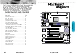


Mainboard User's Manual
Page 37
Page 36
Mainboard User's Manual
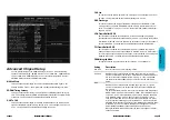
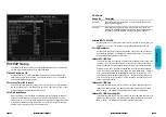
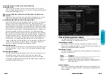
PCI/PnP Setup
Choose PCI/Plug and Play Setup from the AMIBIOS Setup screen to display the
PCI and Plug and Play Setup options, described below.
Plug and Play Aware O/S
Set this option to Yes to inform AMIBIOS Setup that the operating system can
handle plug and play (PnP) devices. The settings are No or Yes. The Optimal
and Fail-Safe default settings are No.
PCI Latency Timer (PCI Clocks)
This option specifies the latency timing (in PCI clocks) for PCI devices installed in
the PCI expansion slots. The settings are 32, 64, 96, 128, 160, 192, 224, or 248.
The Optimal and Fail-Safe default settings are 64.
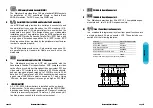
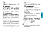
PCI VGA Palette Snoop
When this option is set to Enabled, multiple VGA devices operating on different
buses can handle data from the CPU on each set of palette registers on every
video device. Bit 5 of the command register in the PCI device configuration space
is the VGA Palette Snoop bit (0 is disabled). For example: if there are two VGA
devices in the computer (one PCI and one ISA) and:
Allocate IRQ To PCI VGA
Set this option to Yes to allocate an IRQ to the VGA device on the PCI bus. The
settings are Yes or No. The Optimal and Fail-Safe default settings are Yes.
PCI IDE Bus Master
Set this option to Enabled to specify that the IDE controller on the PCI bus has
bus mastering capability. The settings are Disabled or Enabled. The Optimal
and Fail-Safe default settings are Disabled.
Offboard PCI IDE Card
This option specifies if an offboard PCI IDE controller adapter card is used in the
computer. You must also specify the PCI expansion slot on the motherboard
where the offboard PCI IDE controller card is installed. If an offboard PCI IDE
controller is used, the motherboard onboard IDE controller is automatically dis-
abled. the settings are Disabled, Auto, Slot1, Slo, Slot3, Slot4, Slot5, or Slot6. If
Auto is selected, AMIBIOS automatically determines the correct setting. The
Optimal and Fail-Safe default settings are Auto. This option forces IRQ 14 and
15 to a PCI slot on the PCI local bus. This is necessary to support non-compli-
ant PCI IDE adapter cards.
Offboard PCI IDE Card
This option specifies the PCI interrupt used by the primary IDE channel on the
offboard PCI IDE controller. The settings are Disable, Hardwired, INTA, INTB,
INTC, or INTD. The Optimal and Fail-Safe default settings are Disabled.
Offboard PCI IDE Secondary IRQ
This option specifies the PCI interrupt used by the secondary IDE channel on the
offboard PCI IDE controller. The settings are Disabled, Hardwired, INTA, INTB,
INTC, or INTD. The Optimal and Fail-Safe settings are Disabled.
VGA Palette
Snoop Bit
Disabled
Enabled
Description
Data read and written by the CPU is only directed to the PCI VGA
device’s palette registers.
Data read and written by the CPU is directed to the both the PCI
VGA device’s palette registers and ISA VGA device palette registers,
permitting the palette registers of both devices to be identical.


