


Mainboard User's Manual
Page 33
Page 32
Mainboard User's Manual
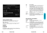
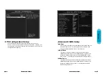
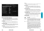
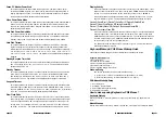
Advanced Chipset Setup
Choose Chipset Setup on the AMIBIOS Setup main menu. All Chipset Setup
options are then displayed. AMIBIOS Setup can be customized. AMIBIOS Setup
can be customized. AMIBIOS Setup can be customized via AMIBCP. See the
AMIBIOS Utilities Guide for additional information.
MA Wait State
This option specifies the length of the delay inserted between MA signals. The
settings are Slow or Fast. The Optimal and Fail-Safe default settings are Slow.
SDRAM Timing Latency
This option specifies the latency for the Synchronous DRAM system memory sig-
nals. The settings are Auto (AMBIOS automatically determines the optimal delay)
or Manual. The Optimal and Fail-Safe default settings are Auto.
RAS To CAS
This option specifies the length of the delay inserted between the RAS and CAS
signals of the DRAM system memory access cycle. The settings are 2 CLKs ro 3
CLKs. The Optimal and Fail-Safe default settings are 3 CLKs.
CAS Lat.
This option sets the latency period for the CAS signal. The settings are 2 CLKs or
d3 CLKs. The Optimal and Fail-Safe default settings are 3 CLKs.
RAS Precharge
This option specifies the length of the RAS precharge part of the DRAM system
memory access cycle when EDO DRAM system memory is installed in this com-
puter. The settings are 3 CLKs or 4 CLKs. the Optimal and Fail-Safe default set-
tings are 4 CLKs.
VGA Frame Buffer USWC
Set this option to Enabled to enable the VGA video frame buffer using USWC
(Uncacheable, Speculatable, Write-Combined) memory. The settings are Enabled
ro Disabled. Older ISA VGA card drivers may not behave correctly if this option is
not set to Disabled. The Optimal and Fail-Safe default settings are Disabled.
PCI Frame Buffer USWC
Set this option to Enabled to enable the USWC memory attribute and improve
video performance when a PCI video adapter is installed. However, VGA card dri-
vers may not behave correctly when this option is set to Enabled. The settings are
Disabled or Enabled. The Optimal and Fail-Safe defaults are Disabled.
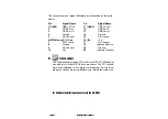
DRAM Integrity Mode
This option sets the type of system memory checking. The settings are:
Setting
Non ECC
ECC Only
ECC
Description
No error checking or error reporting is done.
Multibit errors are detected and reported as parity errors. Single-bit
errors are corrected by the chipset. Corrected bits of data from memory
are not written back to DRAM system memory. If Level I is selected,
the J25 External SMI software jumper on the Series 745 board is dis-
abled.
Multibit errors aer detected and reported as parity errors. Single-bit
errors are corrected by the chipset and are written back to DRAM sys-
tem memory.
If a soft (correctable) memory error occurs, writing the fixed data back to
DRAM system memory will resolve the problem. Most DRAM errors are
soft errors. If a hard (uncorrectable) error occurs, writing the fixed data
back to DRAM system memory does not solve the problem. In this
case, the second time the error occurs in the same location,m a Parity
Error is reported, indicating an uncorrectable error. If ECCI is selected,
AMIBIOS automatically enables the System Management Interface (SMI)
is enabled. If you do not want to enable power management, set the
Power Management/APM option to Disabled and set all Power
Management/APM to Enabled and set the power management timeout
options as desired.


