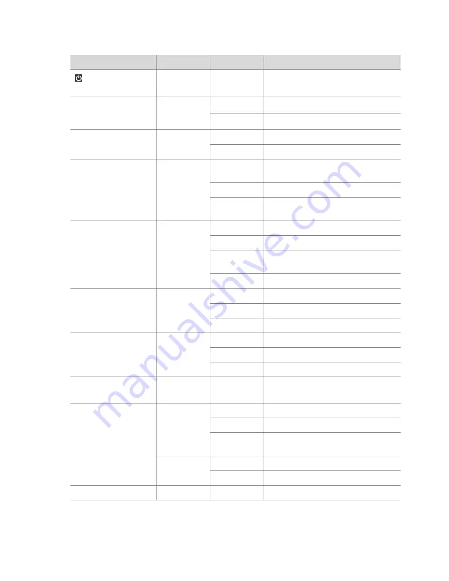
background image

2


Table


1

1


Status


Indicators


Indicators


Color


Status


Description


(Power


indicator)


Red


Constantly


on


Device


powered


on.


NET


(network


indicator)


Blue/Green


Constantly


on


Network


properly


connected.


Off


No


network


connection.


PWR


(power


indicator)


Blue/Green


Constantly


on


Power


connected.


Off


No


power.


IR


(remote


control


indicator)


Blue/Green


Constantly


on


Device


is


selected


and


can


be


remotely


controlled.


Blinking


Device


is


being


verified.


Off


Device


is


not


selected


and


cannot


be


remotely


controlled.


SHIFT


(reuse


button


indicator)


Blue


Constantly


on


The


reuse


button


becomes


a


function


key.


Briefly


on


A


button


is


pressed


and


released.


Off


The


reuse


button


works


in


number


or


letter


input


mode.


Briefly


off


A


button


is


pressed


and


released.


RUN


(running


indicator)


Blue/Green


Constantly


on


Running


normally.


Blinking


Starting.


Off


Shut


down.


CODEC


(codec


indicator)


Blue/Green


Constantly


on


Signal


input


without


coding


or


decoding.


Blinking


Being


encoded


or


decoded.


Off


No


signal


input


or


system


shutdown.


ENC


(Encode


indicator)


Green


Blinking


Encoding.


HD


(hard


disk


indicator)


Blue/Green


Constantly


on


Running


properly


without


data


access.


Blinking


Running


properly


with


data


access.


Off


Hard


disk


is


not


installed


or


the


system


shuts


down,


or


the


indicator


turns


red.


Red


Constantly


on


Hard


disk


at


fault.


Blinking


Several


hard


disks


at


fault


or


array


rebuilt.


HD


ERR


Red


Constantly


on


Hard


disk


at


fault.


Summary of Contents for DVR300-08E

Page 1: ...DVR200 300 Series Digital Video Recorders User Manual Manual Version 100 20140128 Zhejiang Uniview Technologies Co Ltd...

Page 2: ...onventions Used Symbol The symbols in this chapter are shown in the following table They are used to remind the reader of the safety precautions during equipment installation and maintenance Safety Sy...

Page 3: ...e camera should be packed in its original packing z Improper use or replacement of the battery may result in hazard of explosion Please use the manufacturer recommended battery type Caution Fiber opti...

Page 4: ...ion LVD EMC Directive This product complies with the European Low Voltage Directive 2006 95 EC and EMC Directive 2004 108 EC WEEE Directive 2002 96 EC ste Electrical Electronic Equipment WEEE irective...

Page 5: ...ters 22 Configuring Audio and Video Parameters 26 Configuring Encoding Parameters 27 Configuring OSD Parameters 28 Configuring ROI 32 3 Preview 32 Man Machine Interface Output 33 Automatic Detection 3...

Page 6: ...Type 72 Boolean Alarm 72 Motion Detection Alarm 74 Occlusion Detection Alarm 77 Video Loss Alarm 79 Device Alarm 80 Configuring the Triggered Action 81 Alarm Triggered Sound 81 Alarm triggered Email...

Page 7: ...nformation 107 System Backup 108 Refreshing USB Storage Information 109 Creating a USB Flash Drive Folder 109 Deleting a USB Flash Drive File or Folder 110 Exporting the System Configuration and Datab...

Page 8: ...ine interface cannot be modified For the specific parameters that are grayed out see the man machine interface z For devices of different models the functions may be different so refer to the actual d...

Page 9: ...on A button is pressed and released Off The reuse button works in number or letter input mode Briefly off A button is pressed and released RUN running indicator Blue Green Constantly on Running normal...

Page 10: ...ning the button counterclockwise is equivalent to pressing the up key DIRECTION z Move between different menu items shift the focus in PTZ mode move the PTZ up down left or right after the PTZ tool ba...

Page 11: ...hide the PTZ or playback toolbar SCREENS In preview and playback mode used to switch between different screens Screens 3 5 and 7 show videos in the corridor MAIN AUX Used to switch between man machin...

Page 12: ...orming service operations ensure that you have corresponding operation permissions For details about permission configuration refer to User Configuration 1 Right click anywhere in the preview interfac...

Page 13: ...ls about how to use the mouse and the remote control refer to How to Operate the Mouse and How to Operate the Remote Control The method for operating the buttons on the front panel is similar to the m...

Page 14: ...ICK Used to access the right click context menu SEQUENCE Used to start stop polling switching in preview mode PLAYBACK Used to enter the video playback interface and display the playback toolbar in pr...

Page 15: ...step 3 Press Device on the remote control enter the remote control ID of the device and then press OK If the device can receive the command from the remote control the IR LED turns green and now you c...

Page 16: ...of the mouse for at least 3 seconds and then release the right button to switch the displays screen of the man machine interface For details about the screen switching sequence refer to Automatic Dete...

Page 17: ...ording to steps 3 to 5 Steps Screenshot 1 Confirm whether to start the wizard during next power on and then click Next NOTE If you do not select the Start wizard when device starts checkbox the power...

Page 18: ...k interface card NIC to configure its IP address subnet mask and default gateway Keep the default settings of the rest network parameters unless otherwise stated 3 Click OK after the configuration is...

Page 19: ...rest system parameters unless otherwise stated 3 Click OK after the configuration is complete If the management mode is changed the device will be restarted 5 Configure storage parameters Click Storag...

Page 20: ...zation Array area and then click Virtualize NOTE It takes a while to virtualize an array Wait patiently After the virtualization is complete the Virtualized column of the array is displayed as Yes in...

Page 21: ...nnot overlap or include each other 6 After configuring all parameters click Finish to save the configuration Then you can perform various service operations Table 2 1 Description of Important Paramete...

Page 22: ...n in a visual chart of storage configuration Allocated GB Storage resource capacity allocated to the camera or expanded for the camera Note Capacity expansion is applicable only to cameras to which st...

Page 23: ...ace and then choose Menu Camera The video channel interface is displayed 2 Search for IPCs Click Search The IPC search interface is displayed When you access the IPC search interface a quick search is...

Page 24: ...supports automatic discovery otherwise the adding operation fails z The displayed parameters vary according to different types of IPCs That is the parameters displayed for a Uniview IPC are different...

Page 25: ...IPCs Access Mode Access mode of Uniview IPCs The default value is Uniview You can also set the access mode to ONVIF as necessary Password Password for the user admin to log in to the IPC web interfac...

Page 26: ...2 Manually add IPCs Click Add The Add Modify IPC interface is displayed z Add Uniview IPCs Select Uniview from the Vendor drop down list box and enter relevant parameters For details about important...

Page 27: ...oding parameters z Encoding configuration Set the parameters of video streams according to different stream packages supported by the device z OSD configuration Set parameters for masking and OSD cont...

Page 28: ...meter Description PTZ Protocol PTZ protocol that the PTZ camera supports Address Code Address code of the PTZ camera In order to control the PTZ camera you need to decrease the address code of the PTZ...

Page 29: ...3 NOTE To delete a camera bound to an analog channel select the channel and then click the En Disable button in the Channel Management interface Make sure that Disabled is displayed in the Channel col...

Page 30: ...iview IPCs and third party IPCs are different 4 Click Ok The configuration is saved z The figure on the right shows the camera parameters for the analog channel For details about the important camera...

Page 31: ...the IPC web interface Confirm Confirmed password for the user admin to log in to the IPC web interface Protocol Transport protocol for real time streams The default is UDP You may change the value to...

Page 32: ...review interface and then choose Menu Configuration Serial Port Configuration and then configure the serial port mode Multicast IP Multicast Port IP address and port number of the multicast group for...

Page 33: ...nfigure audio and video parameters Click the Audio Video tab select a channel from the Channel Select drop down list box and configure audio and video parameters Mirror Mode is only applicable to came...

Page 34: ...select a channel from the Channel Select drop down list box and configure encoding parameters The parameters displayed for analog channels uniview IPCs and third party IPCs are different For third pa...

Page 35: ...s its encoding rate according to image quality Stream Smoothen Whether to enable the stream smoothening function Note z This parameter is effective when a digital channel is selected z When the networ...

Page 36: ...onfigure OSD parameters 1 Click the OSD tab and set parameters For details about the parameters see Table 2 6 NOTE The parameters to be set vary according to different device types Therefore the actua...

Page 37: ...dle of the screen at first and then set the valid mask area z Select Mask Area from the PTZ control panel on the 3D Area Mask interface and click To Mask Area to move the mask area to the middle of th...

Page 38: ...ontent in this area will be masked Note To set a mask area click Set to enter the preview state at first hold and drag the left button of the mouse to draw the image area to be masked and hold the mas...

Page 39: ...Select drop down list box 2 Click Set beside Area to enter the channel preview state 3 Hold and drag the left button of the mouse to draw a rectangular frame to set a valid area After setting the area...

Page 40: ...IDEOOUT1 VIDEOOUT2 Primary Port 1 DVI 2 HDMI 3 VGA 4 VIDEOOUT1 5 VIDEOOUT2 NOTE z All possible ports are listed above Some types of devices however do not have certain types of ports Therefore the act...

Page 41: ...etection relationship described in Automatic Detection States on the Preview Interface In the preview interface the recording alarm and other states of various channels are presented and differentiate...

Page 42: ...s Button Description Stop Video Click this button to stop playing the video in the current pane PTZ control Click this button when the pane is in preview state The PTZ control interface is displayed M...

Page 43: ...erations Menu Option Description Screenshot Camera You can choose this menu option to start or stop the preview of a digital channel such as an IPC Note When the camera connected through the channel i...

Page 44: ...mple of Auto Switch Operation Auto switch means outputting corresponding images for preview on the preview interface of the monitor according to the cameras configured in the current screen splitting...

Page 45: ...n the preview interface and choose Multi screen to set the new screen splitting mode Then the device starts polling switching from the first screen according to the new screen splitting mode Preview C...

Page 46: ...r example admin Camera 1 20130320 09 15 12 001 jpg indicates the image captured by the user admin at 09 15 12 on March 20 2013 and 001 indicates that it is the first picture captured at 09 15 12 Digit...

Page 47: ...erface Right click anwhere in the preview interface of a normal size and then choose Exit to end the digital zoom operation Configuring Preview Parameters In general you can start preview after comple...

Page 48: ...ng the default number of screens after power on Enable Auto switch indicating whether to enable polling switching Auto switch Interval indicating the polling switching interval and Substream First ind...

Page 49: ...re preferred in multi pane mode When this function is enabled in multi pane preview mode secondary streams are previewed for a camera with dual streams whereas primary streams are previewed for a sing...

Page 50: ...configure the parameters of virtual channels For details about important parameters see the table below NOTE z The bound port shown in the figure on the right is for your reference only The actual bou...

Page 51: ...nly and the actual PTZ control operations available for a PTZ camera depend on the functions of the PTZ camera and the PTZ protocol that the PTZ camera supports For example some vendors use some prese...

Page 52: ...icates the lowest speed and 9 indicates the highest speed Preset position Shows a list of preset positions You can select the preset position for the PTZ Patrol Shows a list of PTZ camera patrol route...

Page 53: ...ete a preset position Deletes a preset position Set a home position Sets the home position and auto back home position time of the PTZ If the preset position is set to None it indicates that no home p...

Page 54: ...t first For details refer to 2Configuring Channel Parameters z When entering the number and description of the preset position ensure that the number of the preset position is not identical with any e...

Page 55: ...or the patrol route and then click Add The Add Patrol Route interface is displayed 3 Enter the name of the patrol route 4 Click Add select a preset position of the PTZ camera set the duration for the...

Page 56: ...ng a patrol route you can modify or delete it The method for modifying a patrol route is similar to the method for adding a patrol route Configuring a patrol plan Before configuring a patrol plan add...

Page 57: ...el list 3 Click Configure The patrol plan configuration interface is displayed 4 Configure general plans and exception plans For details about important parameters see Table 4 2 After configuring the...

Page 58: ...ception Plan drop down list box and then click Delete schedule Starting Patrol You can manually call a certain patrol route to execute the patrol operation or start a patrol plan so that the PTZ camer...

Page 59: ...l plan is preempted during manual patrol The original patrol plan is not restored until the PTZ is released Configuring PTZ Parameters In general PTZ control can be performed according to default syst...

Page 60: ...the specific parameters Table 4 3 Description of Major Configuration Parameters of a Camera Configuration Type Parameter Description Basic configuration PTZ Auto Release s When the PTZ is not preempt...

Page 61: ...preview interface choose Menu Configuration Serial Port Configuration and then configure the serial port mode 5 Recording You can perform the recording operation after completing quick configuration F...

Page 62: ...face choose Menu Manual Record select the channel for which manual recording has been started and then click Stop The system stops recording the audio and video captured through the selected channel P...

Page 63: ...isplayed 2 Start a storage plan Select the channel whose storage plan needs to be started and click Start The data of the channel is stored according to the storage plan 3 Stop a storage plan Select a...

Page 64: ...te Steps Screenshot 1 Right click anywhere in the preview interface and then choose Menu Storage Information The storage information interface is displayed 2 Check the recording state of each camera i...

Page 65: ...t settings of arrays can be restored Creating and virtualizing an array It is not recommended that you perform any device configuration operation when creating an array Steps Screenshot 1 Right click...

Page 66: ...the availability and recoverability of user data to the utmost extent It is slow to build an RAID1 array One RAID1 array can be built with only two hard disks of the same capacity z RAID5 Multiple har...

Page 67: ...ilt and the idle slot 2 Click Rebuild and confirm the operation The array is rebuilt NOTE When an array is being rebuilt the array list shows the rebuilding state and the current rebuilding progress W...

Page 68: ...resources For details refer to Deleting Storage Resources and Configuring Storage Resources Steps Screenshot 1 Right click anywhere in the preview interface and then choose Menu Storage Array The arr...

Page 69: ...ore configuring the storage plan configure storage resources for the camera at first For details refer to20 Configuring Storage Resources Steps Screenshot 1 Right click anywhere in the preview interfa...

Page 70: ...xception plan select the plan from the Exception Plan drop down list box and then click Delete schedule Deleting Storage Resources CAUTION After you delete storage resources the storage plans and reco...

Page 71: ...yback Video Playback This function is used to play videos stored in the hard disk s of the device on a pane Before you use this function verify that the corresponding camera has recorded videos Steps...

Page 72: ...can comprehensively collect and analyze information for this period of time Before performing synchronous playback verify that the corresponding cameras have video resources Steps Screenshot 1 Right...

Page 73: ...ituation of a date selected from the calendar Steps Screenshot 1 Right click a pane in the preview interface A menu is displayed Choose Playback The video playback interface is displayed 2 Query video...

Page 74: ...me Channel selection Selects one or more channels to be queried which are displayed as camera names Query Queries video resources stored on the selected channels Displays the current play progress Not...

Page 75: ...tured image file username camera name and current recording time_record jpg For example admin Camera 2 20130320 09 15 12 002 _record jpg indicates the image captured by the user admin at 09 15 12 on M...

Page 76: ...play Release the left button of the mouse The selected area is zoomed in NOTE Right click the zoomed in area to restore the area to the state before zooming in or repeat steps and to zoom in other are...

Page 77: ...ission z The hard disk of the device has stored videos Steps Screenshot 1 Right click anywhere in the preview interface and then choose Menu Recording The Recording Backup interface is displayed 2 Que...

Page 78: ...If the duration of the video is less than half an hour the device saves the video as one file if the duration is longer than half an hour the device splits the video by half an hour and saves them as...

Page 79: ...oolean Alarm Set the Boolean alarm and configure the guard plan for the device according to site requirements Steps Screenshot 1 Right click anywhere in the preview interface and then choose Menu Alar...

Page 80: ...e its name triggering mode and duration For parameter description see Table 8 1 Then click Ok to finish the Boolean output configuration 4 Select a Boolean item for alarm triggering configuration and...

Page 81: ...r Description Trigging mode z Normal On The Boolean item is a low level alarm z Normal Off The Boolean item is a high level alarm Note The parameter value must match the external third party Boolean i...

Page 82: ...iew interface and then choose Menu Alarm Motion Detection The motion detection alarm configuration interface is displayed 2 Start the motion detection alarm function Select a target camera and click S...

Page 83: ...form other operations 4 Click Ok to save the configuration and return to the Motion Detection interface under Alarm Configuration NOTE The higher the sensitivity the higher the level The camera can de...

Page 84: ...e tramper proof area you set for video images of a camera is blocked When the occlusion detection alarm function is enabled you need to set an alarm area and alarm sensitivity and configure the guard...

Page 85: ...state 2 Hold the left button of the mouse and drag the mouse to draw a rectangular frame as a valid area The default valid area of the system is the full screen 3 Select an area and right click it to...

Page 86: ...d when video signals of a channel are lost so that you can handle the alarm in time The video loss alarm function can work around the clock without relying on any guard plan Steps Screenshot 1 Right c...

Page 87: ...Device alarm including temperature alarm fan failure alarm and anti disassembly alarm can work around the clock without relying on any guard plan Device alarms can be associated with audible alarms o...

Page 88: ...mperature alarm and anti disassembly alarm not available for DVR200 are deployed around the clock and cannot be withdrawn Alarms will be reported when the corresponding alarm functions are enabled Con...

Page 89: ...ect the alarm type Select the Alarm Type tab for which an alarm triggered action needs to be configured and click Trigger Action The Alarm triggered Action interface is displayed 3 Enable the audible...

Page 90: ...n interface is displayed 3 Enable the email sending function For information about email configuration refer to Email Server 4 Click Ok The configuration is saved Alarm triggered Boolean Output This c...

Page 91: ...eeds to be configured and click Trigger Action The Alarm triggered Action interface is displayed 3 Configure alarm triggered Boolean output items 1 Click the Output Boolean tab The alarm triggered Boo...

Page 92: ...ger Action The Alarm triggered Action interface is displayed 3 Configure the alarm triggered storage function 1 Click the Storage tab The alarm triggered storage configuration interface is displayed 2...

Page 93: ...reset position 1 Click the Preset tab The configuration interface for setting the alarm triggered preset position for the PTZ is displayed 2 Select a PTZ camera for which an alarm triggered preset pos...

Page 94: ...arm triggering If the preview pane associated with live viewing is not visible in the current screen splitting mode the device automatically switches the screen splitting mode and displays the minimum...

Page 95: ...o add all preview panes to be associated The figure on the right is for your reference only The actual interface may be different 4 Click Ok The configuration is saved Configuring the Guard Plan You c...

Page 96: ...isplayed 3 Configure general and exceptional plans On the day of the exceptional plan only the guard plan in the exceptional period is executed On the other days the general guard plan is executed z A...

Page 97: ...ts IP address subnet mask and default gateway 4 Click OK NOTE After the NIC eth0 is configured system services are restarted PPPoE Steps Screenshot 1 Right click anywhere in the preview interface and...

Page 98: ...gured on the UNP server NOTE Before configuring the IP address through UNP ensure that the device communicates normally with the UNP server Email Server Steps Screenshot 1 Right click anywhere in the...

Page 99: ...and then choose Menu Network Basic The basic configuration interface is displayed 2 Configure route parameters 1 Click Set in the Route Configuration area The route configuration interface is displaye...

Page 100: ...l can be used only after the device code passes the authentication PTZ Auto Release s When the PTZ is not preempted by any other user with higher permissions and the user currently controlling the PTZ...

Page 101: ...Note It is recommended that you enable cache control when network delay or intermittent interruption exists or when stream smoothing is enabled on the encoding device Configuring the Server Only the...

Page 102: ...communications protocol set on the central server in actual networking Configuring NTP Only the user admin can configure the NTP function Steps Screenshot 1 Right click anywhere in the preview interfa...

Page 103: ...ine the system can also obtain the model information about the device z The parameters to be set may vary depending on the device model Therefore the actual pages may be different Steps Screenshot 1 R...

Page 104: ...set to Transparent Channel Destination IP Destination Port IP address and port number of the port at the other end of the transparent channel Note The two parameters can be set only when the serial po...

Page 105: ...priority has the highest permission to preempt resources Steps Screenshot 1 Right click anywhere in the preview interface and then choose Menu Configuration User The user configuration interface is d...

Page 106: ...After being deleted a user cannot log in to the system again If the user has logged in before being deleted the user is forcibly logged out Modifying User Information Only the user admin can modify us...

Page 107: ...cking or Unlocking Users Only the user admin can lock or unlock users You can lock some users so as to prevent these users from logging in to the device Steps Screenshot 1 Right click anywhere in the...

Page 108: ...anywhere in the preview interface and then choose Menu Configuration User The user configuration interface is displayed 2 Log out a user forcibly Select the user to be logged out forcibly and click Lo...

Page 109: ...on the man machine interface is the same as that on the web interface When the login password on the man machine interface is changed the password on the web interface is changed accordingly Steps Sc...

Page 110: ...to be changed The Change User interface is displayed Enter the user password and confirmed password and then click Ok to finish the operation 11 Device Maintenance Querying History Alarms You can view...

Page 111: ...or set any combination of these parameters and then click Query The history alarms meeting the condition are displayed 3 View alarm triggered recordings 1 Click Recording The Recording List interface...

Page 112: ...bout TFTP or FTP upgrade refer to the Release Notes that comes along with the version The following sections only describe how to perform local upgrade z Local upgrade The system is locally upgraded t...

Page 113: ...rom the Image Path drop down list box 2 Click Upgrade and confirm the upgrade operation The version upgrade starts After the upgrade is complete the device automatically restarts You can check the lat...

Page 114: ...ry at most system operation logs of at most 30 days System Information You can check device states in real time to facilitate device maintenance Right click anywhere in the preview interface and then...

Page 115: ...en the device is in server management mode Note This parameter is visible to the user admin only System Backup Only the user admin can perform system backup That is the user admin can back up or expor...

Page 116: ...tion and click Refresh The current capacity and directory information about the partition are displayed Creating a USB Flash Drive Folder Steps Screenshot 1 Right click anywhere in the preview interfa...

Page 117: ...eate the folder Deleting a USB Flash Drive File or Folder CAUTION Data is permanently deleted after you delete a file Therefore exercise caution with this operation Steps Screenshot 1 Right click anyw...

Page 118: ...then select the file or folder to be deleted 3 Delete the target file or folder Click Delete A dialog box is displayed Click Yes to confirm the deletion operation Exporting the System Configuration an...

Page 119: ...e area After a while the system prompts that the export succeeds and generates the file confdb tar gz in the directory Till now the export operation is finished CAUTION If the name of the exported fil...

Page 120: ...le backup_runlog tar gz in the directory Till now the export operation is finished CAUTION If the name of the exported file already exists a prompt is displayed indicating whether to overwrite the exi...

Page 121: ...or the Database area and confirm the import operation CAUTION When the configuration file is imported the system restarts In this process ensure that the device is not powered off If the device is su...

Page 122: ...port the IPC configuration file Click Import in the IPC area and select the XML file to be imported Then click Yes to confirm the import operation Restoring the Default Configuration Only the user adm...

Page 123: ...saving mode If the device will not be used for a long time it is recommended that you cut off the power supply You can soft shut down the device by pressing the POWER ON OFF button on the front panel...

Page 124: ...device code check That is if you enter 255 during the check the check will be successful no matter whether the device code is matched If the device can receive the command from the remote control the...

Page 125: ...correct z Check whether the PTZ address is correct 13 Appendix Menu Structure Figure 13 1 Menu Structure Menu Backup Configuration Camera Storage Alarm Network Maintenance Help Basic Preview Array Sto...

Page 126: ...ording through a network ISP Internet Service Provider JBOD Just a Bundle Of Disks A stack of multiple disks which provides storage resources for the external network It does not support any RAID poli...

Page 127: ...nt Disks A type of multi disk management technology which provides high performance storage function featuring high data reliability at a moderate cost RAID5 A distributed parity redundancy technology...

Page 128: ...http www uniview com en globalsupport uniview com...

Reviews: