Camille Bauer LINAX A325, Operating Instructions Manual
The Camille Bauer LINAX A325 is a cutting-edge industrial product offering precise measurement and control capabilities. Ensure optimal performance with our comprehensive Operating Instructions Manual, available for free download at manualshive.com. Access the manual instantly and unlock the full potential of your Camille Bauer LINAX A325.
Share
Download


Reviews:
No comments
Related manuals for LINAX A325

DS-2CE19U8T-IT3Z
Brand: HIKVISION Pages: 16

H.264 DVR
Brand: Danbit Pages: 120

D16CX
Brand: Speco Pages: 93

4713218632821
Brand: Avtech Pages: 17

QT428
Brand: Q-See Pages: 98
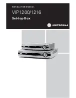
SET-TOP BOX VIP1216
Brand: Motorola Pages: 27

DCT3080
Brand: Motorola Pages: 2

DCT3400 Series
Brand: Motorola Pages: 2

DCT3416
Brand: Motorola Pages: 2

DCX3501-M
Brand: Motorola Pages: 16

QIP27 Series
Brand: Motorola Pages: 33

DCT6400 Phase III
Brand: Motorola Pages: 41

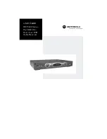
VIP 1910
Brand: Motorola Pages: 16

DCX3400 Series
Brand: Motorola Pages: 2

DCT6400 Series
Brand: Motorola Pages: 62
DCT6400 Series
Brand: Motorola Pages: 43

DCH3416
Brand: Motorola Pages: 48

DCX3400 Series
Brand: Motorola Pages: 55


