Operating instructions
6057 758 101b
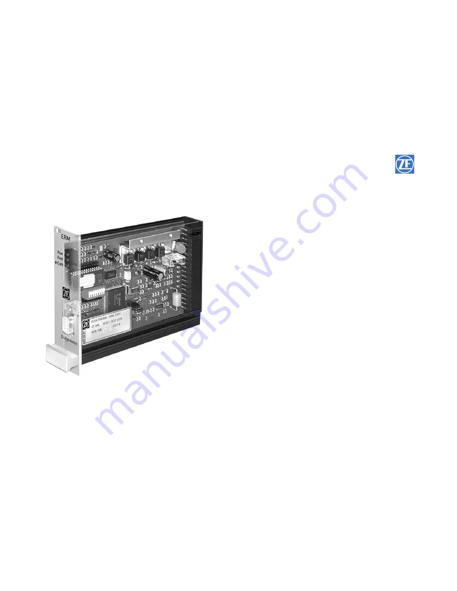
ZF Electronic Control Unit ERM
Page 1: ...Operating instructions 6057 758 101b ZF Electronic Control Unit ERM...
Page 2: ...ed by copyright Any kind of reproduction or dissemination in whatever form that does not exclusively correspond to documen tation objectives will be prosecuted if no prior approval by ZF Friedrichshaf...
Page 3: ...ions Personnel required to carry out repairs on ZF products must receive appropriate training in advance It is the responsibility of each company to ensure that their repair staff is properly trained...
Page 4: ...orking procedures Pictures drawings and components are not to scale Conclusions about size and weight should not be drawn even within a complete illustration Always follow the working steps as describ...
Page 5: ...oop torque 23 3 2 1 Function diagram 23 3 2 2 Pin assignment 24 3 2 3 Technical instructions 25 3 2 4 Startup 25 3 3 Operating mode controlled with sensing 26 3 3 1 Function diagram 26 3 3 2 Pin assig...
Page 6: ...A Ra min 500 Frequency input input resistance RE 3 3 k Switching threshold low to high 11 5 V DC Switching threshold high to low 4 0 V DC Ambient temperature 0 to 50 C Storage temperature 30 to 70 C H...
Page 7: ...6057 758 101 2005 02 7 Electronic control unit ERM Technical Data 35 128 182 5 170 111 5 92 Installation dimensions 015242...
Page 8: ...tilting 2 Tighten screws 1 4 so that the cooling attachment on the board contacts the metal rack and thus ensures optimum heat dissipation NOTE Do not exceed permissible tightening torque to avoid boa...
Page 9: ...Electronic control unit ERM Technical Data 6057 758 101 2005 02 9 1 2 3 4 015239...
Page 10: ...on DIL switch position 5 0 and 6 1 LED Contr flashes if the setting procedure has not been carried out in the operating mode calculation or sensing Connection for Diagnostic connector for ZF MOBiDIG t...
Page 11: ...nit ERM Technical Data 6057 758 101 2005 02 11 1 2 3 OPEN 4 5 6 7 8 017182 Program memory 1 2 3 Jumper Data memory E2PROM Terminal strip Microprocessor Connection for diagnostic unit DIL switches Cool...
Page 12: ...trol unit ERM OPEN 1 2 3 4 5 6 7 8 PNP Stop Set PNP fv fn 10 k 10 k 11 17 18 10 12 13 7 9 5 8 1 2 6 1 2 3 Jumper 14 15 14 15 16 7 9 5 8 24 V to 36 V Soll Ist 015241 Example for external analog input e...
Page 13: ...k 47 k Type magnetoresistive potentiometer for voltage input nom value also wire potentiometer can be used Jumper Position Appropriate function is activated by inserting a jumper NOTE Pos 1 and 2 must...
Page 14: ...PIN Function 9 voltage input nominal value 0 to 10 V input resistance Ri 200 k Input may also be supplied by external analog sources provided the voltage refers to ground PIN 5 and the max value does...
Page 15: ...te output voltage 24 V DC max load 50 mA max load impedance 10 k A suppressor diode must be used with inductive load no varistor input current max load current 1 to 2 mA For functions consult relevant...
Page 16: ...nstant in accordance with the nominal value input Operating mode open loop control torque The DIL switches must be set to suit unit size Y Y Y Y see page 18 Torque is set and kept constant in accordan...
Page 17: ...en production speed is reached NOTE If a frequency 3 Hz is already reached during a setting procedure no reference values will be transferred LED 3 continues flashing Frequency range 3 1000 Hz Stored...
Page 18: ...1 0 4 0 15 0 1 1 0 EBU 0 3 0 75 0 4 1 1 1 0 EBU 1 1 25 1 1 0 0 0 1 EBU 3 1 25 3 3 1 0 0 1 EBU 10 1 5 12 0 0 1 0 1 EBU 30 2 2 39 0 1 0 0 1 EBU 60 G 1 5 82 0 0 1 0 1 EBU 200 G 2 2 268 0 1 1 0 1 EBU 250...
Page 19: ...for force control e g no travel tension sensor PID for position or force control Electronic control unit ERM Description 6057 758 101 2005 02 19 Coding DIL switch 1 2 3 4 5 6 7 8 0 0 Coding DIL switc...
Page 20: ...ction diagram Operating modes Electronic control unit ERM 6057 758 101 2005 02 20 015234 015236 ZF Hysteresis brake Tensile force F N Roller Current I A ZF electronic control unit Feed rate v m s Nomi...
Page 21: ...1 2005 02 21 11 10 16 6 12 13 7 9 5 8 1 2 17 18 24 to 36 V ZF electronic unit ERM Nominal traction Hysteresis brake clutch Designation PIN connection Voltage supply plus 24 36 V 17 18 Voltage supply g...
Page 22: ...s within the range given under 1 Technical Data see page 6 3 Check polarity plus minus CAUTION Unpermitted voltage and polarity may damage the installation 4 Switch off operating voltage 5 Connect the...
Page 23: ...ction diagram Electronic control unit ERM Operating modes 6057 758 101 2005 02 23 015243 ZF Hysteresis brake Tensile force F N Roller Current I A ZF electronic control unit Feed rate v m s Nominal tra...
Page 24: ...assignment 11 10 16 6 12 13 7 9 5 8 1 2 17 18 24 to 36 V ZF electronic unit ERM Nominal traction Hysteresis brake clutch Designation PIN connection Voltage supply plus 24 36 V 17 18 Voltage supply gr...
Page 25: ...Data see page 6 3 Check polarity plus minus CAUTION Unpermitted voltage and polarity may damage the installation 4 Switch off operating voltage 5 Connect the ERM 6 Switch on operating voltage Power L...
Page 26: ...758 101 2005 02 26 U Ist 015233 015236 017181 ZF Hysteresis brake Tensile force F N Sensor Roller Current I A ZF Electronic control unit Feed rate v m s Nominal traction actual U Sensor zero position...
Page 27: ...3 7 9 5 8 1 2 17 18 Designation PIN connection Voltage supply plus 24 36 V 17 18 Voltage supply ground 1 2 actual sensor 7 5 grinder 8 Nominal traction sensor 7 5 grinder 9 Set key 11 17 18 Hysteresis...
Page 28: ...is within the range given under 1 Technical Data see page 6 3 Check polarity plus minus CAUTION Unpermitted voltage and polarity may damage the installation 4 Switch off operating voltage 5 Connect th...
Page 29: ...ner diameter Q diameter ratio U voltage difference Set UDa nominal by potentiometer 8 Set max roller 9 Push set key 10 Release set key Reference is accepted contr lights up 11 The installation is read...
Page 30: ...es Electronic control unit ERM 6057 758 101 2005 02 30 n 015237 ZF Hysteresis brake Tensile force F N Roller Current I A ZF Electronic control unit Feed rate v m s Nominal traction v 017181 TN Calc va...
Page 31: ...e supply plus 24 36 V 17 18 Voltage supply ground 1 2 Nominal traction sensor 7 5 grinder 9 Friction factor 7 5 grinder 8 Roller speed fn 12 Feed rate fv 13 Set key 11 17 18 Hysteresis brake 16 6 11 1...
Page 32: ...ncy 3 Hz see jumper position measured on PIN 17 18 Compensation of friction With minor traction installation friction may be relatively high compared to the brake torque needed This must be considered...
Page 33: ...must light up contr must flash 7 Set max roller speed and production speed 3 Hz 8 Push set key 9 Release set key Reference is accepted contr lights up 10 Installation is ready for operation NOTE Shoul...
Page 34: ...odes Electronic control unit ERM 6057 758 101 2005 02 34 015230 015231 ZF Hysteresis brake Tensile force F N Dancer Roller Spring Weight force Current I A ZF Electronic control unit Feed rate v m s Da...
Page 35: ...n Voltage supply plus 24 36 V 17 18 Voltage supply ground 1 2 Actual traction sensor 7 5 grinder 8 Nominal traction sensor 7 5 grinder 9 Stop key 10 17 18 Hysteresis brake 16 6 11 10 16 6 12 13 7 9 5...
Page 36: ...ck polarity plus minus CAUTION Unpermitted voltage and polarity may damage the installation 4 Switch off operating voltage 5 Connect the ERM 6 Switch on operating voltage Power LED and Feedb LED must...
Page 37: ...ication Use Max power e g for emergency stop Zero power e g for start up Activation of additional functions Jumper on ERM board must be in Pos 2 Pos 1 must not be connected cf 1 4 Jumper position Inpu...
Page 38: ...controlled see page 33 with calculation Power LED does not No operating voltage or too low Check operating voltage light up ERM fuse is defective Replace defective fuse Program does not run correctly...