


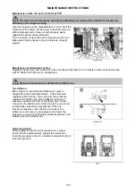


3. Deaeration of the brakes of the rear wheels
Parking brake adjustment
MHS16N046
Before adjustment of the hand brake secure the tractor against movement with wedges and release the hand
brake. There is a vertical position of the lever (A). Set the length of the pull rod (B = 130 mm); the length is
measured from the centre of the pins according to the figure. Adjust the pull rod (B) for the right brake on the
other side as well. Adjust the pull rod (C) with the solid end of bowden so that its length from the centre of the
pin to the bracket is (C = 198 mm). Finely adjust the full overstrain or clearance of the hand brake using the
bowden adjusting nut (D) so that the clearance between the pin of the lever (A) and pull rod (B) is 1 mm. Lift
up both rear wheels of the tractor, secure the lever of the hand brake to the fifth claw of the ratchet wheel
and try to turn one wheel; the wheels must not turn. If the wheels are turning, check adjustment of the pull
rods and finely adjust with the screw (D), if appropriate. When the hand brake is released, both wheels must
rotate freely. Asymmetry of braking effects must not be higher than 20%.
Use the following procedure:
1. Check the amount of the brake fluid in the equalizing
vessel and add the missing amount of a new liquid to the
max. amount.
2. Remove the rubber cap, install the hose on the
deaeration screw (1) of the brake cylinder and immerse its
other end to the bottom of the transparent vessel partly
filled with the brake fluid (2). The deaeration screw must
be permanently under pressure to prevent air penetration
through its threads. During this operation place the vessel
at least 300 mm above the deaeration screw.
3. Release the deaeration screw by 1/4 revolution max.
4. Press down the pedal on the deaerated side fully and
tighten the deaeration screw.
5. Release the brake pedal and repeat the procedure until
no air bubbles come out of hose.6. Repeat the procedure
on the other side.
MHS16N079
ADJUSTMENT
125
Summary of Contents for MAJOR HS Series
Page 1: ...OPERATOR S MANUAL MAJOR HS 1 2017 80 Tractor is Zetor Since 1946 1 2017 1 2017 ...
Page 3: ...2 ...
Page 9: ...8 ...
Page 11: ...NOTES 10 ...
Page 41: ...NOTES 40 ...
Page 47: ...NOTES 46 ...
Page 63: ...NOTES 62 ...
Page 93: ...NOTES 92 ...
Page 97: ...Placement of fuses in fuse box MHS16N107 ELECTRIC INSTALLATION 96 ...
Page 101: ...NOTES 100 ...
Page 109: ...NOTES 108 ...
Page 135: ...NOTES 134 ...


