background image

2 Installing, commissioning and testing

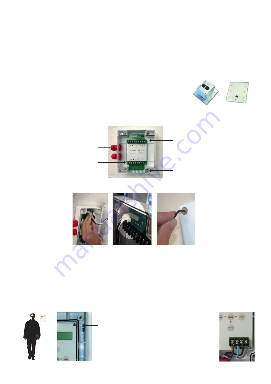
step 1 mounting the head

Screw the head backing plate to the wall - always try to use as sturdy a location as possible, such 
as brick or major structural steels (avoid mounting to outer metal cladding etc). Avoid mounting the 
head where direct sunlight can shine directly into the ‘eyes’ of the beam (care should be taken when 
mounting in glass atriums). Ambient sunlight will not affect the beam.

Also available - unistrut adapter plate

Use this accessory for easy mounting to unistrut fabrication. Holes are pre-
drilled to the correct pitch of the head and conveniently positioned for use 
with unistrut.

step 2 mounting the controller

Important

 mount the controller at eye level and ensure easy access.

Screw in through holes provided outside of the 
rubber seal. Wire to head using colour coded 
terminals. 

If this connection is not made ERROR 

will appear on the controller, this connection can 
be checked by reading the resistance across the 
black and grey terminals, they will read 110 ohm if 
OK or 220 ohm if not connected properly.

2 knock-outs are provided on 
both sides. 

Take care when using 

drills not to damage the circuit 
board.

Screw the head screws 
down with the 3mm 
allen key provided. 

Your 

wiring should be flush 
and not flattened by 
tightening down screws.

Wire to low level controller using 
bottom colour coded terminals.

Wire into system as required (see 
generic wiring diagram on the 
following page). 

Ensure that all 

wiring is below the level of the 
front edge of the box.

Screw in through holes provided 
outside of the rubber seal.

Connect the head 
to the base plate by 
first plugging in the 
connector. 

Do not

 force 

in, whitewires should be 
uppermost. 

Should you 

forget to connect this 
the controller screen 
will read ERROR.

To avoid damaging the detector head never dangle the front 
cover assembly from the ribbon

Important 

ensure the 

connector is this way up

Summary of Contents for Zeta Beam

Page 1: ...The ZetaBeam Protection System Xtra User Guide 0150 01...

Page 2: ...rt range mask supplied on the single reflector 7 to 70 metres the standard ZetaBeam The standard ZetaBeam comes boxed with the head unit low level controller key and quick start installation guide thi...

Page 3: ...t along its entire axis Note Careful design consideration should be made when positioning beams and reflectors in environments that can be susceptible to condensation i e warehouses near to water that...

Page 4: ...ction is not made ERROR will appear on the controller this connection can be checked by reading the resistance across the black and grey terminals they will read 110 ohm if OK or 220 ohm if not connec...

Page 5: ...To re panel To controller EOL FIRE Fire LED Auxiliary no relay contact 2A 30Vdc used for External LED switching no c nc no c nc fault fire controller interface external reset fire technical support 44...

Page 6: ...ne beam To controller Beams 1 2 3 To controller To re panel no c nc no c nc fault fire controller interface external reset fire technical support 44 0 1582 608000 manufactured by Lemtronics Sdn Bhd Ph...

Page 7: ...raw it may be necessary to use normal mode to prevent excessive current draw Fast mode allows x4 times faster motor response and it may be quicker to commission each beam in turn Once commissioning is...

Page 8: ...ill assume it has found the far wall You will need to identify and move the obstruction or reconsider the positioning of the ZetaBeam You can identify that the beam is obstructed by the right hand fig...

Page 9: ...the angle of the beam Y until you receive an AQ of over 100 Re ector is lower than the beam head use Y to bring the beam onto the re ector Beam head Re ector y x x y Manual AQ 125 X 0 000 Y 0 000 Manu...

Page 10: ...and would normally be below 0 90 If this is not the case you may need to start the Manual Alignment process again to return both the zetabeam axis to 0 00 and identify and remove the obstruction Air Q...

Page 11: ...ding the resistance across the black and grey terminals if connected it should read 110ohms if not connected at one end this will read 220ohms This screen will appear when the beam is performing a sel...

Page 12: ...o return signal is received the beam will reach full power and the screen will say Pre Align complete If you don t receive high enough output power and receiver sensitivity readings this will usually...

Page 13: ...uto reset The beam is factory set to auto reset when the received signal raises above the fire threshold hysteresis This can be set to latching if your system requires this Change by using the right a...

Page 14: ...before it returns to normal This action prevents small fluctuations in returned signal causing the beam to fall in and out of a fire state This can be adjusted between 1 and 40 by using the right and...

Page 15: ...g needs to be maintained in the beam path use the right and left keys to turn the system on and off This will show as a fault on the panel Press enter to return to beam maintenance 5 Press enter to go...

Page 16: ...s Electrical Specifications Supply Voltage 12 to 30 VDC Supply Current 3 5mA constant current in all operational states Constant Current 17mA constant current in fast commissioning Environmental Speci...

Reviews: