background image


-12- 

5. 

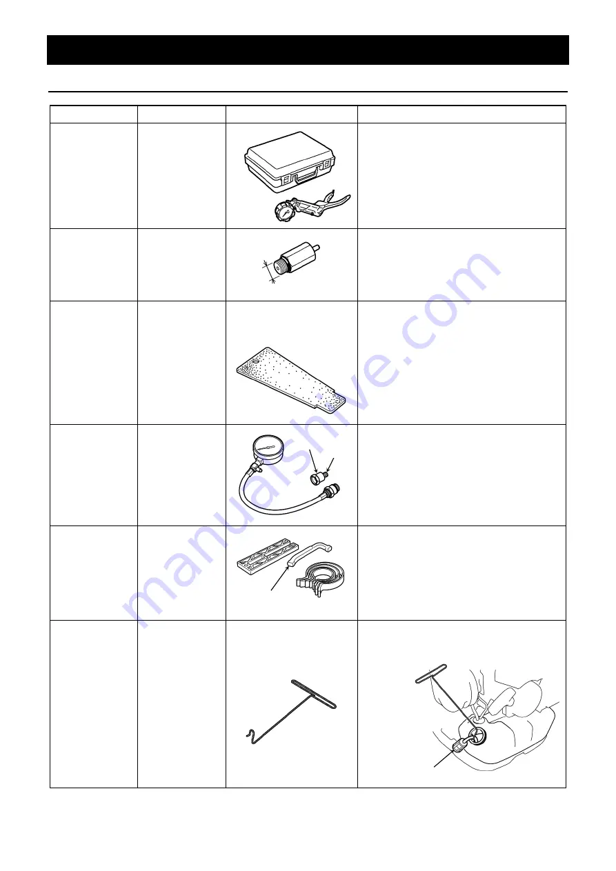
Special Tools


5-1 Description 

Tool Name


Tool Number


Appearance


Usage


Pressure 
Vacuum Gauge


H531030623 


Engine seal check (see page 19)


Pressure Tester 
Attachment


H503844001 


Set in the hole of the spark plug, and 
connect the pressure gauge   
(see page 19).


Outlet Cover 
Plate


H502541102 


Closure of exhaust port and inlet port       
(see page 19) 

Compression 
Gauge (

φ

14mm)


Adapter Size: 
(

φ

10mm) 

H531031686 


583 84 98-01 


Compression pressure check 


(see page 18)


Piston Fitting Kit 

H502507001 


Piston installation (see pages 17 and 20)


Fuel Filter Hook


H502508301 


Suspending the fuel filter


Fuel Filter 

φ

10


Adapter 

φ

10


Stopper 

Do not use. 

φ

10


Summary of Contents for EBZ7500

Page 1: ...Workshop Manual 2017 EBZ7500 8500...

Page 2: ...re also included in this manual However many cases need rich maintenance experience and informed judgment Please refer to this manual for maintenance support WARNING 1 The contents of this manual are...

Page 3: ...gnition Coil Installation 30 7 6 Coupling Installation 31 7 7 Carburetor Installation 31 7 8 Fan Installation 32 7 9 Recoil Starter Installation 32 7 10 Engine Cover Installation 33 7 11 Intake Hose I...

Page 4: ...fan The fan uses a half closed fan optimizing the air flow with the new flat volute case realizing the very best of the air volume and wind velocity Intake from the side of the frame Guard Net New ty...

Page 5: ...ed EBZ7500 8500 The new spiral type flexible hose has no sharp on its surface contrary to the conventional flexible hose It is hard to split and has excellent durability In addition wind resistance is...

Page 6: ...EBZ8500 The fresh air intake system is used Because the clean air in the volute case is taken in directly through the dedicated passage it is powerful and the maintenance interval can be lengthened 1...

Page 7: ...oah s Strato charged engine adopts air guided stratified scavenging system which introduces leading air to the scavenging port separately from the air fuel mixture The leading air pushes out the combu...

Page 8: ...egins its downstroke after top dead center a scavenging port starts to open and lead air in the scavenging port moves into the cylinder earlier than the air fuel mixture 3 As the piston begins its ups...

Page 9: ...35 6 1 Guard Net Removal see page 21 7 12 Frame Installation see page 34 7 17 LHD Throttle Lever Set Assembly see page 40 7 8 Fan Installation see page 32 7 15 Elbow Installation see page 36 7 11 Inta...

Page 10: ...ary coil short circuiting Switch Push type Cooling System Forced air cooling Air Cleaner Element Type Primary Dry puff Secondary Dry paper Two stage filters Output Axle Rotation Direction Counterclock...

Page 11: ...4 Technical Data 4 2 External Dimensions Unit mm Models A B BB C D EBZ7500 354 536 479 499 1198 EBZ8500 357 535 497 540 1198 Illustration shown is EBZ7500 Reference...

Page 12: ...iam d3 Outer diam D4 Outer diam D5 Length L2 EBZ7500 99 5 99 5 349 97 4 99 103 340 EBZ8500 Part No 576 56 49 01 576 56 50 01 576 57 64 01 Name Straight Pipe Pipe End Pipe End Appearance Air velocity t...

Page 13: ...0 Ignition coil setting Air gap see page 15 Rod Assy 516 18 29 01 1101 96220 Piston pin removal or installation see page 16 Bearing Guide 577 40 98 01 Main bearing installation see page 16 Crankshaft...

Page 14: ...ug and connect the pressure gauge see page 19 Outlet Cover Plate H502541102 Closure of exhaust port and inlet port see page 19 Compression Gauge 14mm Adapter Size 10mm H531031686 583 84 98 01 Compress...

Page 15: ...e into the cylinder from the plug hole to stop the movement of the piston 4 Remove the mounting nut of the rotor NOTE Turn the rotor counterclockwise CCW slowly contact the piston head to the recoil r...

Page 16: ...movement of the piston 3 Remove themounting nut of the coupling NOTE Turn the coupling counterclockwise CCW slowly contact the piston head to the recoil rope lightly and loosen the nut 4 Set the pulle...

Page 17: ...the reference values for resistance tester measurement The resistance value within the normal range shows no internal leakage or any other defect Ignition Checker Tool No 3699 90247 We supply the meas...

Page 18: ...milar S Starter side 1 Set the support special tool outside of the crankcase S as shown 2 Tap the bearing with a plastic hammer lightly and fit it into the crankcase horizontally 3 Insert the bearing...

Page 19: ...rankshaft into the bearing while screwing the nut NOTE After press rotate the crankshaft to check the operation of the bearing If the movement of the bearing is heavy tap the bolt head with a plastic...

Page 20: ...he bearing 9 Compression Pressure Check 1 Warm up the engine for at least 5 minutes NOTE After warm up the engine and the muffler will become hot Be careful not to burn yourself 2 Remove the attachmen...

Page 21: ...ttachment special tool to the cylinder 4 Remove the intake cup the carburetor and the gasket 5 Temporarily install the carburetor and the intake cup and insert the outlet cover plate special tool betw...

Page 22: ...the sealing should be fine NOTE After installing the muffler operate the engine by wide open throttle more than one minute and retightening the mounting bolts 11 Piston Installation When inserting the...

Page 23: ...crew head will be damaged 2 Insert the flat tip screwdriver between the guard net and the frame twist the screwdriver to pull out the clip and remove the guard net from the frame NOTE Do not damage th...

Page 24: ...se F If necessary gently tap with a plastic hammer to the crankcase F 2 Remove the crankcase F from the crankcase S with the crankshaft NOTE The crankshaft cannot be removed from the crankcase F in th...

Page 25: ...earing Removal Check wear of the oil seal rattling and seizure of the bearing If necessary replace them If the bearing press fitting portion of the crankcase is worn replace the crankcase at the same...

Page 26: ...er surface and lip of the oil seals Degrease the outer surface of the main bearings and the bearing contact surface of the crankcase Degrease the taper and thread portion of the crankshaft Degrease th...

Page 27: ...C position the keyway of the shaft is downward and the short taper is the crankcase F side Insert the crankshaft into the crankcase F using the crankshaft installing tool of special tool see page 17 C...

Page 28: ...with the rod assy of special tool see page 16 Fit the snap ring in the groove of the piston firmly and turn the end gap of the snap ring to the opposite side of the notch After the assembly check that...

Page 29: ...r make sure to apply the liquid gasket to the mating surface with the cylinder and install the scavenging port cover NOTE The liquid gasket should be applied continuously without any gaps to ensure hi...

Page 30: ...the tap 3 Degrease the thread portions and apply a new thread lock to the mounting bolt or screw NOTE When tightening the bolt with the old thread lock having stuck damage the thread portions of the e...

Page 31: ...have accumulated on the spark arrester with a wire brush If necessary replace it with a new one Torque 2 0 3 0N m 20 30kgf cm 7 4 Rotor Installation 1 Parallel the flat surface of the key to the cent...

Page 32: ...pecial tool between the rotor magnet metal and ignition coil Tighten the mounting bolts while pushing the ignition coil against the rotor see page15 Torque 2 5 4 0N m 25 40kgf cm NOTE Tighten the moun...

Page 33: ...esion of oil or dust on the tapered surface and the threaded portion of the crankshaft and coupling 3 Tighten the mounting nut and fix the coupling Torque 24 5 34 3N m 250 350kgf cm 7 7 Carburetor Ins...

Page 34: ...en the four mounting bolts with equal torque in diagonal order 7 9 Recoil Starter Installation Fit the recoil starter to the crankcase and fix it with the mounting bolts Torque 2 94 4 41N m 30 45kgf c...

Page 35: ...r insert the lower edge of the muffler gasket inside the engine cover to protect the fuel tank from exhaust heat 7 11 Intake Hose Installation Before installing the intake hose apply grease to the air...

Page 36: ...f the lower dampers into the frame and press the upper damper firmly to the frame side 3 Tighten the mounting nuts of the lower dampers Torque 3 92 4 94N m 40 50kgf cm 4 Tighten the mounting screws of...

Page 37: ...on Make sure that the protruding length from the grommet is the specified dimension If protrudes too much or extends too little pipe bending and or poor fuel filter response may occur Connect the retu...

Page 38: ...the elbow Loosen the bolts of the elbow mounting portion of the volute case Insert the elbow between the volute case and the volute cover tighten the loosened bolt and attach the elbow to the volute c...

Page 39: ...Make the gap of the spring hook b and the boss of the recoil case about 2mm Apply grease to the boss Grease Cold resistant grease No 2 or equivalent 3 Insert a rope through the reel as shown in the fi...

Page 40: ...to the groove under the reel Grease Cold resistant grease No 2 or equivalent Reference The groove on the bottom side of the reel is positioned between the notch and the knot of the rope 6 Lightly turn...

Page 41: ...el with your thumb 11 Detach the rope from the notch of the reel stretch it with the knob and release the thumb and slowly wind up the rope to the reel with the spring tension NOTE When the rope is fu...

Page 42: ...m 4 Align the stopper portion of the throttle lever at the lever operation range A of the throttle arm and insert the throttle lever in the hole of the throttle arm 5 Set the wave washer and the lever...

Page 43: ...ottle cable and connect the wire end to the lever plate 9 Attach the throttle cable end to the groove of the throttle arm 10 Push the switch cords into the groove of the throttle arm and set the stopp...

Page 44: ...ock washer may need to be pushed more again when control lever returns automatically during operation Control lever operating torque 0 41 0 52N m 4 2 5 3kgf cm 4 Match the color of the switch cords an...

Page 45: ...hrottle lever and the control lever make sure that the control lever can move fully NOTE Make sure that the tip of the lever spring is hooked under the wire end connecting portion of the throttle leve...

Page 46: ...valve side mm 12 2 Choke valve side mm 14 5 Inlet Valve Opening pressure kgf cm2 kPa 1 3 2 3 127 226 Reseating pressure kgf cm2 kPa 0 6 1 6 59 157 Idling speed range rpm 1 800 2 200 1 900 2 100 No loa...

Page 47: ...Gasket Metering Lever Limiter Cap Idle Adjustment Screw Limiter Cap Body Assy Metering Diaphragm Air Purge Body Priming Pump Pump Cover Idle Adjustment Screw Adjustment of the idle engine speed Turn D...

Page 48: ...ceiving portion and valve portions of the diaphragm are stiff replace it with a new one 3 Inlet Valve Leaking Test Connect the pressure gauge special tool to the inlet port of the carburetor body assy...

Page 49: ...lve and check for dirt sludge rusting and or step wear Replace the inlet valve if a beveled edge is found on the rubber tip Inspect the clogging of the fuel passage in the carburetor body and make sur...

Page 50: ...dle Remove the limiter cap with the limiter cap tool see page 50 Remove the H needle check the wear and damage of the tip and screw portions and if necessary replace it with a new one Clean the cloggi...

Page 51: ...e of the plunger contact surface and inspect for any grooves or scratches where the tip of the screwdriver catches If there are grooves replace the throttle valve assy with a new one 11 Jet Needle Che...

Page 52: ...stnment screw counterclockwise CCW until its tip just touches throttle valve stop then turn it clockwisely CW to the position where the engine speed gets slightly higher Turn the L needle counterclock...

Page 53: ...screw Models Peak Idling rpm WYA 236A EBZ7500 2 700 200 WYA 237A EBZ8500 2 700 100 Set the engine speed at 2 000 200 rpm by turning the L needle counterclockwise CCW Models Rich Down rpm WYA 236A EBZ...

Page 54: ...0 200 WYA 237A EBZ8500 7 250 50 NOTE If the engine speed is too high acceleration failure and output will decrease The ignition coil is digital control misfire type and when the engine speed is too hi...

Page 55: ...on pin and piston pin hole mm 0 005 0 021 0 05 MM CG Replace Piston Ring End gap at cylinder skirt mm 0 15 0 35 0 6 TG Replace Width mm 1 2 1 1 MM Replace Piston Pin Diameter mm 12 11 98 MM Replace Co...

Page 56: ...ake Cup Carburetor M5 60L 3 4 5 30 45 Recoil Starter M5 16L Apply 3M 2353 12mm 3 4 5 30 45 Starter Pulley 2 9 3 9 30 40 Rotor M10 1 0 Hex nut 25 35 250 350 Ignition Coil M4 22L 2 5 4 25 40 Coupling M1...

Page 57: ...air or replace Switch 1 Switch is OFF ON the switch 2 Switch failure Replace 3 Primary wiring ground Repair or replace Sparks appear in the spark plug Compression and fueling are normal 1 Over sucking...

Page 58: ...Disassemble and clean 3 Water mixed with fuel Drain and apply new fuel Revolution rises suddenly and stops 1 Lack of fuel Refill 2 Clogged breather Clean 3 Clogged carburetor Clean 10 3 Engine cannot...

Page 59: ...ed with dusts Clean 4 Improper fuel Change with proper fuel 5 Carbon deposited inside of combustion chamber Clean 6 Spark plug electrode red hot Clean thoroughly and adjust spark gap to 0 6 to 0 7mm O...

Page 60: ...thers Trouble Probable Cause Countermeasure Poor fuel consumption Clogging of the pre filter and the paper filter Pre filter Wash with hot water containing neutral detergent and dry Paper filter Clean...

Reviews: