Touch-MyDesign
Technical Support:
http://zennioenglish.zendesk.com
5
Once the input terminal and the KNX terminal are connected, the device can be easily
mounted on the metallic plate by the action of the built-in magnets. After that, it is
necessary to slide Touch-MyDesign downwards to fix it through the security anchorage
system.
Finally, it is advisable to check that the device is properly installed, and that only the
profile of the device becomes visible from above, from below and from both sides (the
metallic plate should be completely hidden).
This device does not need any external power supply since it is powered through the
KNX bus.
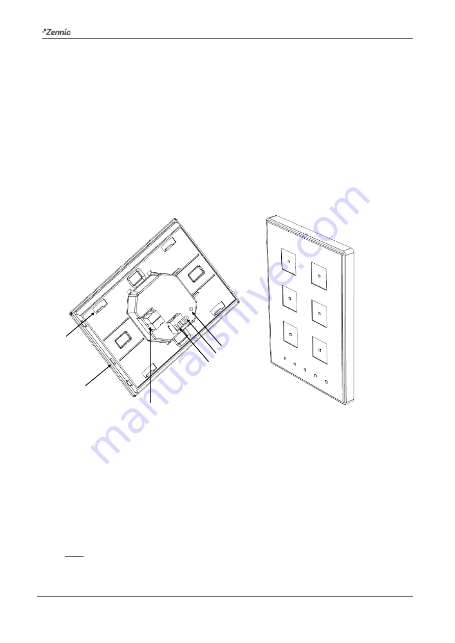
Figure 3
Touch-MyDesign. Element diagram.
The programming button (5) shown in
may be pressed with the help of a thin
screw to set Touch-MyDesign in
programming mode
. After a short press, the
programming LED will light in red. Note that if this button is held while plugging the
device into the KNX bus, the device will enter the
secure mode
. The LED will then
blink in red.
Note: whenever the device recovers the bus power, an immediate self-calibration
process of the touch panel takes place. Please ensure to avoid making pressure over
the front glass while powering the device. If undesired effects arise during use, please
1
2
3
4
5
6
1.
Magnet.
2.
Internal temperature probe.
3.
KNX clamp.
4.
Analogue/digital input clamp.
5.
Programming button.
6.
Programming LED.


