background image

 
ZENN

iO

 AVANCE Y TECNOLOGÍA 


www.zennio.com


3. CONFIGURATION 

3.1.  BASIC CONTROL  

With  KLIC-DI,  the  air  conditioning  unit  can  be  monitored  and  controlled  the  same 

way it is done with the wired remote control provided with the air conditioning unit.  

By means of bus KNX, it can be controlled the following basic functionalities of the 

air conditioning system: 


ON/OFF

 of the air conditioning unit. 


Setpoint Temperature

. Between 16 and 32 ºC. 


Operating Mode

: Auto, Heat, Dry, Fan and Cool. 


Fan Speed

: 2 or 3 speed levels configuration. (Check out the available levels in 

the Daikin unit) 

These functionalities  have  associated  a  machine  status,  which  is  periodically  sent 

to  KLIC-DI. When  KLIC-DI  receives  a  status  different from  the  previous  one  from  the 
machine, it updates the status of the corresponding parameter in the bus KNX. 

3.2.  ADVANCED FUNCTIONALITIES 

Besides  the  basic  control  over  the  air  conditioning  system,  KLIC-DI  offers  other 

advanced  functionalities  that  give  an  added  value  with  regard  to  the  wired  remote 
control: 


Scenes  Configuration:

  allows  establishing  a  specific  parameters 

combination for the air conditioning machine. 


Temperature  Limitation

:  Daikin  air  conditioning  systems  are  limited  in 

temperature  (usually  to  the  range  16-32  ºC.  Please  verify  the  range  for  a 
particular  model  in  the  corresponding  Daikin  manual).  This  KLIC 
functionality  allows  configuring  custom  temperature  ranges  for  the  modes 

Heat

  and 

Cool

  by  means  of  the  ETS  in  such  a  way  that  the  setpoint 

temperature will remain in the range. In case of receiving from the bus KNX 
a  temperature  command  with  a  value  out  of  the  configured  limits,  the 
temperature value sent to the machine will be the corresponding limit value. 


Summary of Contents for KLIC-DI

Page 1: ...KLIC DI INTERFACE KNX DAIKIN ZN1CL KLIC DI Edition 4 0 Version 1 4 PRODUCT MANUAL...

Page 2: ...1 Basic Control 8 3 2 Advanced Functionalities 8 4 Parameterization 12 4 1 Default Configuration 12 4 2 General 14 4 3 Mode 15 4 4 Fan speed 15 4 5 Scenes 17 4 6 Temperature Limitation 18 4 7 Automati...

Page 3: ...nication bus of the unit the KLIC DI will communicate with this remote control acting one device as master control while the other device will act as slave control It is important to verify that the K...

Page 4: ...ning functionality Error management handles Daikin error codes as well as any communication errors that may arise LED indicators allow monitoring of the bidirectional traffic flow Integrated EIB KNX B...

Page 5: ...rom Daikin is also used it is necessary to make sure that the wired remote control is in mode slave if the KLIC DI is configured as master control And vice versa if the KLIC DI is configured as slave...

Page 6: ...tes bidirectional communication between KLIC DI and Daikin unit Diagrams Leyend A KLIC DI B Daikin Wired remote control C Daikin SKY or VRV unit P1 P2 Daikin connection bus 1 2 Zennio connection termi...

Page 7: ...emote control Besides including the programming red LED typical in any KNX device the KLIC DI incorporates two more LEDs blue and green ones in order to inform about the bidirectional communication be...

Page 8: ...it updates the status of the corresponding parameter in the bus KNX 3 2 ADVANCED FUNCTIONALITIES Besides the basic control over the air conditioning system KLIC DI offers other advanced functionaliti...

Page 9: ...e Daikin installer it establishes the corresponding auto mode 3 The machine establishes the auto mode according to the average value of the Reference temperature and the Indoor temperature The tempera...

Page 10: ...itial Configuration All machine status must have an initial value after installing the system or a power failure With this purpose it has been included in the KLIC the possibility of defining the init...

Page 11: ...ount When switching the type of control of the Daikin wired control between master and slave it is necessary to remove the power supply from the wired control and connecting it again for rebooting the...

Page 12: ...utton on the device and select Edit Parameters for starting with the configuration In the following sections there is a detailed explanation about each of the different functionalities of the device i...

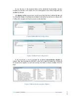
Page 13: ...s and the Simplified Modes Cool Heat are disabled by default while the Fan is configured for 2 different fan speeds and the step control is also disabled In the next figure it can be watched the avail...

Page 14: ...s we select the functionalities in the pull down lists the access to the functionality configuration window will appear in the Menu at the left and the corresponding communication objects are enabled...

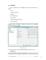
Page 15: ...communication objects for controlling and indicating the Mode that exist by default If the option Individual Modes is activated the operating mode of the machine will be sent by means of the 1 bit Sen...

Page 16: ...ls the fan speed percentages will be interpolated in the following way Initial Speed Percentage Interpolated Speed Percentage Level 0 49 25 Minimum 50 100 100 Maximum Three Levels of Fan On the other...

Page 17: ...the speed level is at 100 the level will remain at this maximum until the speed is decreased 4 5 SCENES A scene involves the synchronized sending of several commands to the air conditioning unit with...

Page 18: ...nge minimum medium o maximum 4 6 TEMPERATURE LIMITATION The air conditioning unit has defined upper and lower temperature limits that cannot be exceeded the limits are usually 32 C and 16 C respective...

Page 19: ...nd the personalized ranges will control the unit performance when it switches on 4 7 AUTOMATIC SWITCH OFF When this option is enabled the air conditioning unit will be temporarily switched off if a st...

Page 20: ...ne status after the installation or a power failure The variables that can be initialized are the following ON OFF Last ON or OFF Temperature Last or custom Mode Last auto heat dry fan or cool Fan Las...

Page 21: ...ZENNiO AVANCE Y TECNOLOG A www zennio com 2 1 Figure 16 Initial Configuration...

Page 22: ...um 1 20 Medium 21 60 Maximum 61 100 Auto 0 Minimum 1 20 Minimum Medium 21 40 Medium 41 60 Medium Maximum 61 80 Maximum 81 100 4 1 bit R T 0 1 ON OFF Status Split State ON OFF 5 2 bytes R T 10 32 Tempe...

Page 23: ...Dry Mode 1 Nothing 0 MODE 13 1 bit I W 0 1 Simplified Mode Cool 0 Heat 1 14 1 bit R T 0 1 Auto Mode Status Auto Mode Enabled 1 Disabled 0 15 1 bit R T 0 1 Cool Mode Status Cool Mode Enabled 1 Disabled...

Page 24: ...339 M2 387 T2 435 X2 4 03 52 E3 100 J3 148 U3 196 73 244 43 292 13 340 M3 388 T3 436 X3 5 04 53 E4 101 J4 149 U4 197 74 245 44 293 14 341 M4 389 T4 437 X4 6 05 54 E5 102 J5 150 U5 198 75 246 45 294 15...

Page 25: ...8 121 L8 169 98 217 68 265 38 313 G8 361 N8 409 V8 457 Y8 26 A9 74 H9 122 L9 170 99 218 69 266 39 314 G9 362 N9 410 V9 458 Y9 27 AA 75 HA 123 LA 171 9A 219 6A 267 3A 315 GA 363 NA 411 VA 459 YA 28 AH...

Page 26: ...E ERROR BUS DAIKIN CODE 41 C8 89 F8 137 P8 185 88 233 58 281 28 329 K8 377 R8 425 W8 473 Z8 42 C9 90 F9 138 P9 186 89 234 59 282 29 330 K9 378 R9 426 W9 474 Z9 43 CA 91 FA 139 PA 187 8A 235 5A 283 2A...

Page 27: ...2 7 2 7 ZENNIO TECHNICAL DOCUMENTATION SIGN UP http zennioenglish zendesk com TECHNICAL SUPPORT...

Reviews: