background image

©2013  DJI  Innovations.  All  Rights  Reserved.                                                                                                                                         

(2) GCU Power Cable 

connection 

Connect the 

GCU Power Cable

 to a connecter, if DJI Multi-rotor is used, 

solder the power cable to the power pad on aircraft.


(3) Gimbal TILT Control channel 

X2 

X1 


4.


Connection has been finished. They can come into use after power on. 


5.


The tilt direction of gimbal can be controlled by one channel of Autopilot System (WKM is X2, NAZA-M and 

NAZA-M V2 is X1). You are asked to set the corresponding channel on your Transmitter, and connect the 

corresponding port of Receiver to the Main Controller. Use the Gimbal Assistant Software to help you with 

configuration. 


Notes: 

(1)


Re-do the Transmitter calibration after NAZA-M Firmware upgrade and double check other items. 

(2)


Make sure to power on the gimbal after camera mounting, since the wrong center of gravity will cause 

motor overheating and then lead to damage. 

(3)


Make sure connections are correct; otherwise may lead to the gimbal normal work or even out of control.


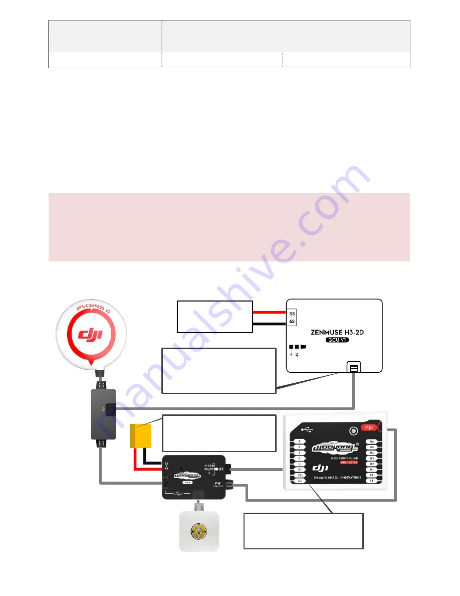
GCU and DJI Autopilot System Connection


positive pole(

+

)

negative pole(-)

Battery
(3S~6S)

Note:

The GCU can be connected to any CAN 
ports on the PMU or to the CAN port on 
the GPS.(Any spare CAN port on the 
WKM system.)

To Battery

Note: 
The PMU and GCU can both connect to 
the same battery of LiPo 3S-6S.

Gimbal TILT Control

Channel X2 is for Gimbal TILT Control, 
connect it correctly, and configure the right 
channel on your Transmitter.


Fig.1 GCU and WKM Connection Diagram 

Summary of Contents for H3-2D

Page 1: ...2013 DJI Innovations All Rights Reserved ZENMUSE H3 2D Gimbal User ManualV1 02 For Firmware V1 00 Assistant SoftwareV1 00 2013 06 19 Revision www dji innovations com...

Page 2: ...as well as to install the assistant software on your computer Please respect the AMA s National Model Aircraft Safety Code As DJI Innovations has no control over use setup final assembly modification...

Page 3: ...DJI F550 and the DJI PHANTOM can use any type Gimbal Controller Unit GCU 1 Connect the gimbal controller to the autopilot system by CAN Bus And Use the 3S 6S power cable to supply power for the GCU a...

Page 4: ...MERA TO THE GIMBAL 7 STEP3 DOUBLE CHECK 7 AUTOPILOT SYSTEM GCU AND GIMBAL WIRING 8 GCU PORT DESCRIPTION 8 STEP1 CONNECT GCU AND AUTOPILOT SYSTEM 8 STEP2 VIDEO SIGNAL TRANSMISSION 11 ASSISTANT 12 STEP1...

Page 5: ...your own aircraft For DJI F450 there are diagrams for your reference 1 Attach the Vibration Absorber to the Top Board of Damper Unit shown in Fig 1 2 Mount the Top Board of Damper Unit to the Bottom...

Page 6: ...position directly determine gimbal performance Please do not adjust the gimbal center of gravity by yourself 4 The gimbal is high precision controlled Do not remove any other screws in the gimbal whi...

Page 7: ...into the System Port of camera and make sure they are in good contact which are marked in Red shown as Fig 2 3 Tighten the M2 5x6 3 screw shown as Fig 3 4 Please put you hand at the position in red m...

Page 8: ...the following table For NAZA M user you are asked to prepare a PMU V2 module Accessory of NAZA M V2 and do some reconnection of the system WKM NAZA M V2 NAZA M 1 Main Controller and PMU connection Co...

Page 9: ...uration Notes 1 Re do the Transmitter calibration after NAZA M Firmware upgrade and double check other items 2 Make sure to power on the gimbal after camera mounting since the wrong center of gravity...

Page 10: ...it correctly and configure the right channel on your Transmitter Fig 2 GCU and NAZA M V2 Connection Diagram Disconnected To Battery Note The PMU and GCU can both connect to the same battery of LiPo 3...

Page 11: ...imbal video power cable to the wireless video transmission unit correctly to avoid the 12V power burn the gimbal or your own device And ensure the cables are insulated to prevent from short circuit Po...

Page 12: ...GCU Communication indicator Blue LED On Without communication Blue LED Blink Communicating with PC Red LED On Disconnected with PC Green LED On Connected with PC Text Description Connection indicator...

Page 13: ...sistant software finishes Upgrade 10 Click OK and power cycle the unit after at least 5 seconds Notes 1 It is recommended to disconnect the connection between the GCU and autopilot during IMU and CMU...

Page 14: ...camera settings 6 Normal connection between GCU and autopilot system 7 Upgrade Autopilot System MC Firmware STEP2 Test 1 Make sure the batteries are fully charged for transmitter GCU and all the othe...

Page 15: ...cted 3 Gimbal mounting direction is disaccording to aircraft nose 2 Connect GCU and autopilot system 3 Ensure Gimbal mounting direction is the same with aircraft nose 2 The gimbal is abnormal after in...

Page 16: ...re System Requirement Windows XP SP3 Windows 7 Windows 8 Mechanical Electrical Characteristics Working Current Static current 400mA 12V Dynamic current 600mA 12V Gimbal Output Power 12V 16 8V Operatin...

Reviews: