


©2013 DJI Innovations. All Rights Reserved.
12
Assistant
STEP1.
Install Driver and Software
1.
Make sure driver is installed correctly, which has been installed before you use WooKong-M, NAZA-M or
NAZA-M V2.
2.
Please download H3-2D gimbal assistant software from
DJI Innovations
website.
3.
Click assistant software Installer and follow the steps to finish installation.
4.
Run the assistant software.
STEP2.
GUI
Connect GCU and PC via a Micro-USB cable, power on GCU.
Communication indicator
·
Blue LED On: Without communication
·
Blue LED Blink: Communicating with PC
·
Red LED On: Disconnected with PC
·
Green LED On: Connected with PC
Text Description
Connection indicator
·
Mouse over each item on the (3) area will display
the corresponding content
1
2
6
5
1
2
6
5
4
3
4
Language
·
中文
or English
Menu
·
Basic: Basic function setting
·
Upgrade: For upgrading the gimbal firmware
·
Info: For version and SN access
3
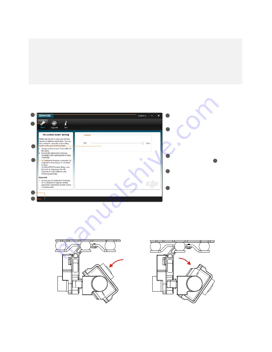
STEP3.
Channel Setting
TILT: Slide the TX switch, the corresponding slider of cursor will move, and you can see the gimbal moving by
rotating the pitch axis, shown as the following chart.
Fig.1 Moving Upwards Fig.2 Moving Downwards


