background image


16 

IFU-001 Rev. 8 

9


S

YSTEM 

T

OOLS


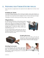
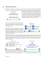
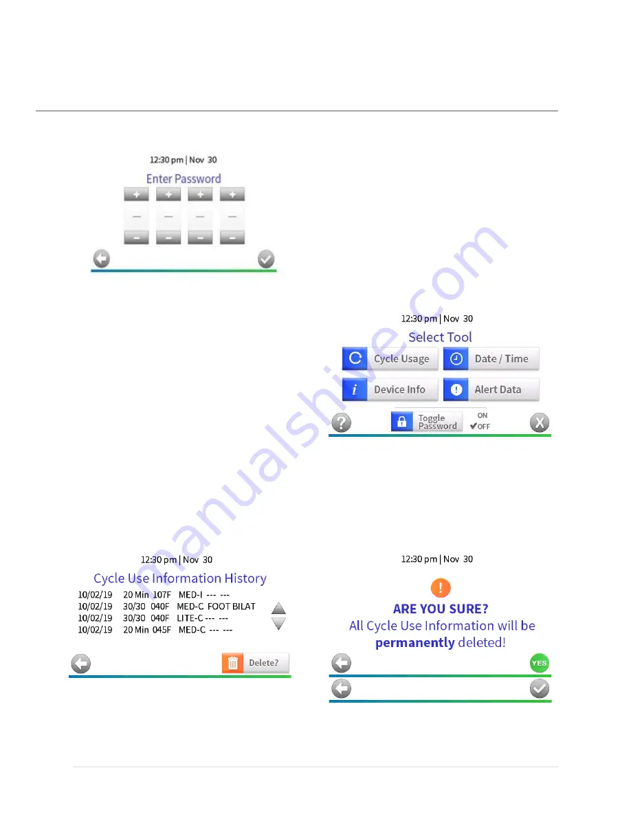
To navigate to the System Tools screen from the Home screen you must first select the 

“Settings” 

button in the lower left corner of your Therm-X touchscreen. A password screen will appear if the 

password  is  enabled.  Use  the  password  that  you 
received with your machine. You will have a maximum 
of  5  attempts  to  input  the  correct  password.  If  too 
many  incorrect  attempts  are  made,  the  machine  will 
display an error and you will need to restart it before 
resuming use of the machine. The Settings screen will 
display immediately if the password is disabled. 


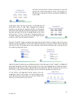
Once you reach the Select Tool screen you will be 

given the selections of “Cycle Usage”, “Date/Time”, 
“Device  Info”,  “Alert  Data”,  “Toggle  Password”, 
“Help”, and “Cancel”. 


The  password  may  be  toggled  on  and  off  by 

selecting the “Toggle Password” button. E

ach time 

the  button  is  selected  the  password  status  will 
change. By enabling the password, you will be able 
to  ensure  that  unauthorized  users  are  unable  to 
change the stored cycle. 

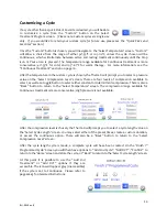
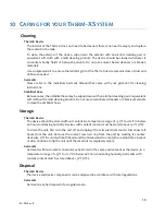
The Cycle Use Information History screen can be reached by selecting the “Cycle Usage” button. It will 

display the past cycles run on the unit which may be scrolled through using the arrows on the right of 

the screen. Additionally, there will be a “Back” button to return you to the Select Tool screen and a 
“Delete?”  button.  The  “Delete?”  button  will  prompt  an  alert  to  confirm  the  previous  cycle’s 

information is deleted.  

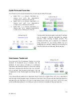
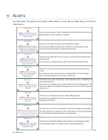
The 

Enter New Date & Time

 screen can be reached 

by selecting the “Date/Time” button. On this screen 

you may select the date 

and time by using the “+” or “

-

 buttons to change the displayed values to the 

Summary of Contents for Therm-X Series

Page 1: ...1 IFU 001 Rev 8...

Page 2: ...1 IFU 001 Rev 8...

Page 3: ...2 IFU 001 Rev 8 Welcome to the Team We re glad you re with us...

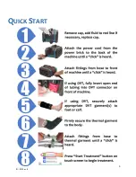
Page 4: ...3 IFU 001 Rev 8 QUICK START...

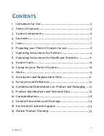
Page 5: ...structions For Healthcare Providers 11 9 System Tools 16 10 Caring for your Therm X System 18 11 Alerts 19 12 Accessories and Replacement Parts 21 13 Acronyms and Definitions 22 14 Symbols and Abbrevi...

Page 6: ...ssionals in rehabilitation facilities outpatient clinics athletic training settings and home settings 2 THERM X FEATURES Please read the entire User Manual before operating the Therm X There are no us...

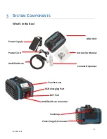
Page 7: ...s in the Box Touchscreen USB Charging Port DVT Port Umbilical Hose connector Tank Cap Power Supply Connector Main Unit Instruction Manual Coolant Dispenser Main Unit Power Supply Instruction Manual Po...

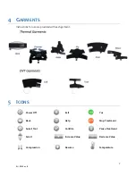
Page 8: ...GARMENTS Instructions for use are provided with each garment 5 ICONS Power Off Exit Yes Back Help Stop Treatment Select Tool Confirm Pause Treatment Scroll Increase Value Decrease Value Compression R...

Page 9: ...t most drug stores Mix 1 gallon 128 ounces of distilled water with 1 pint 16 ounces of 91 isopropyl alcohol to create the Therm X coolant it is recommended to use the Therm X coolant sold by Zenith Te...

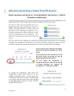
Page 10: ...will feel the garment inflate and fluid flow The Treatment Running screen will appear and will show the current cycle settings a progress bar timer and Stop and Pause buttons The unit will run throug...

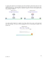
Page 11: ...any times as needed during a cycle Note Temperatures may only be changed to a temperature equal to or closer to room temperature than the programmed treatment Once the prescribed treatment is complete...

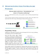
Page 12: ...ram Treatment If the password is enabled you must enter it before proceeding Use the password you received with your machine For more information on passwords please see System Tools on page 16 The Se...

Page 13: ...lected the unit will present the Set DVT Location screen This screen will have options available for Foot and Calf DVT locations as well as a Back button that will return you to the Cycle Selection sc...

Page 14: ...he Select Compression Level screen There are four levels of compression available to select as well as a toggle button to select either constant or intermittent compression There is also a Back button...

Page 15: ...el You can reprogram the Favorite treatment by selecting the Favorite treatment and pressing Reset Favorite Continuous Treatment You may select the Continuous button to set the duration of treatment 1...

Page 16: ...e programmed with any thermal treatment cycle or selected as an independent treatment from the Select Treatment Cycle screen If one DVT garment is being used compression will increase and release thro...

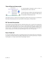
Page 17: ...Data Toggle Password Help and Cancel The password may be toggled on and off by selecting the Toggle Password button Each time the button is selected the password status will change By enabling the pas...

Page 18: ...creen There will also be a Back button to return to the Select Tool screen The Alert Information screen can be reached by selecting the Alert Data button This screen will display the alerts that have...

Page 19: ...duct Do not use solvent based cleaners or abrasive materials to clean the umbilical hose Storage Therm X Device The device should be stored without coolant in a temperature range of 33 F to 122 F in b...

Page 20: ...19 IFU 001 Rev 8 11 ALERTS The table below can guide you through possible alerts you may observe while using your Therm X Home device...

Page 21: ...20 IFU 001 Rev 8...
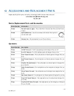
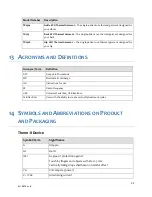
Page 22: ...06 Foot DVT Garment The DVT prophylaxis garment designed for your foot TX0102 Knee Thermal Garment The multi patient use thermal garment designed for your knee TX0105 Back Thermal Garment The multi pa...

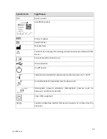
Page 23: ...D DEFINITIONS 14 SYMBOLS AND ABBREVIATIONS ON PRODUCT AND PACKAGING Therm X Device Symbol Term Significance A Ampere Hz Hertz IP21 Degree of protection against Touch by fingers and objects with 12 5 m...

Page 24: ...ed with this device Consult the instructions for use USB connection On Off button Temperature Limitation Temperature must be between 60 F 80 F Humidity Limitation Humidity must be below 60 Atmospheric...

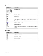
Page 25: ...r Caution There are specific warnings and precautions associated with this device Follow instructions for use Type BF applied part Caution Federal law restricts this device to sale by or on the order...

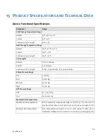
Page 26: ...20 minutes Custom 3 40 minutes Continuous Cycle Length Active 10 40 minutes rest 30 60 minutes Edema Pressure Range Lite 5 mm Hg Low 20 mm Hg Medium 45 mm Hg High 70 mm Hg DVT Pressure Range Calf 50 7...

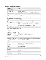
Page 27: ...garments Classifications Information about IEC 60601 1 classification Class of protection against electric shock II Protection against accidental contact and ingress of solid foreign bodies Protectio...

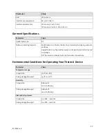
Page 28: ...ylon Ripstop coated in urethane Single Patient Use Thermal Garment 200 Denier Nylon Oxford coated in urethane DVT Garment 200 Denier Nylon Oxford coated in urethane Environmental Conditions for Operat...

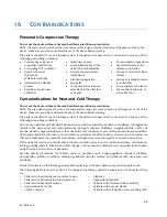
Page 29: ...ted of or observed to have any of the following pre existing conditions Do not use on patients with Raynaud s phenomenon or other vasospastic conditions cold allergy cold agglutinin disorders like par...

Page 30: ...ss on Therm X Do not use near equipment that generates electromagnetic or other interferences as this may be harmful to Therm X Do not smoke or use garments by an open flame Do not stick a finger or a...

Page 31: ...ied correctly may cause the wrap to balloon which may cause damage to the wrap Immediately stop compression therapy if you experience any sense of discomfort numbness or tingling of the limb Use only...

Page 32: ...vironment Guidance RF emissions CISPR 11 Group 1 Therm X uses RF energy only for its internal function Therefore its RF emissions are very low and are not likely to cause any interference in nearby el...

Page 33: ...IEC 1000 4 5 1 kV differential mode 2 kV common mode 1 kV 2 kV Mains power quality should be that of a typical commercial or hospital environment Voltage dips short interruptions and voltage variatio...

Page 34: ...netic site survey a should be less than the compliance level in each frequency range b Interference may occur in the vicinity of equipment marked with the following symbol Radiated RF IEC 61000 4 3 3...

Page 35: ...3 10 3 8 3 8 7 3 100 12 12 23 For transmitters rated at a maximum output power not listed above the recommended separation distance d in meters m can be estimated using the equation applicable to the...

Page 36: ...ew Product and is only for the benefit of a customer Customer who purchases a Product directly from Zenith or from an authorized distributor or authorized seller of Zenith Products SCOPE This Warranty...

Page 37: ...ys after purchase contact Zenith in writing by mail or email customerservice thermxtherapy com and provide Zenith with Customer s contact information model and serial number s of the Product s purchas...

Page 38: ...f business loss of goodwill injury to Customer or patients or clients of Customer or injury to other users of a Product or bystanders to any use even if Zenith is advised of the possibility of such da...

Reviews: