background image

Page 6 of 28 

   802149NZ -  BHA; CHA; CSHA -Installation Instructions - Aug 2015 -  V2.00

Important Safety Instructions

This manual contains important safety, Installation instructions for the Zenith Celsius.

Safety

This appliance is not intended for use by persons (including children) with reduced physical, 
sensory or mental capabilities, or lack of experience and knowledge, unless they have been 
given supervision or instruction concerning use of the appliance by a person responsible for 
their safety. Children should be supervised to ensure that they do not play with the appliance.

For products sold in Europe, this appliance can be used by children aged from 8 years and above and 
persons with reduced physical, sensory or mental capabilities or lack of experience and knowledge if they 
have been given supervision or instruction concerning use of the appliance in a safe way and understand 
the hazards involved. Children shall not play with the appliance. Cleaning and user maintenance shall not be 
made by children without supervision.

Refrigerant

The Zenith Celsius unit contains R134A refrigerant under pressure. Maintenance of the refrigeration unit must 
be carried out by an accredited service provider or qualified refrigeration technician.

Qualifications

If the power cable is damaged it must be repaired only by a qualified technician. To avoid hazards, all 
Installation procedures must be carried out by a suitably qualified tradesperson. The power cable and power 
outlet must be in a safe visible position for connection.

Venting

Sometimes steam and / or condensed droplets may discharge through a vent outlet at the tap. If the tap is not 
installed using the Font pedestal, ensure the tap body is located so the tap outlet safely dispenses into the 
sink bowl area. 

Lifting

Take care when lifting the Zenith Celsius unit. Some units may exceed safe lifting limits. If you feel this is 
beyond your personal capabilities, please seek assistance with the lift. The weights of the units are marked 
on the packaging. Do not lift the unit by the front cover or any connections at the top rear of the unit. Refer to 
the technical specification for the weight of your product. 

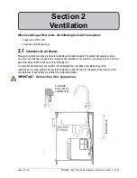
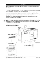
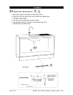
Airflow

The ambient operating temperatures, when installed in a cupboard, must be between 5ºC -  35ºC. The 
system will operate satisfactorily only if proper air ventilation is provided and only if the recommended air 
gaps of 50mm on each side are provided. See section 2 for correct Installation details. 

Frost Protection

If this appliance is located where the ambient air temperature could fall below 5ºC when the unit is not in use, 
do not turn off the appliance electrically. This safeguard does not offer the same protection to the connecting 
pipework and fittings.

ed


Positioning

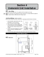
It is important to ensure the undersink unit is positioned in an accessible area close to the floor level. The unit 
must have it’s base mounted in a horizontal position with all inlets and outlets facing up. The Tap must be 
located above the undersink unit. See section 4 for details.

Summary of Contents for Hydrotap G4 Celsius

Page 1: ...15 V2 00 Page 1 of 28 Hydrotap G4 Celsius Installation Instructions Filtered Boiling Chilled and Chilled Sparkling drinking water with unfiltered Hot and Cold ambient water for residential kitchens Af...

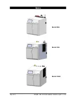
Page 2: ...Page 2 of 28 802149NZ BHA CHA CSHA Installation Instructions Aug 2015 V2 00 Models Model BHA Model CHA Model CSHA...

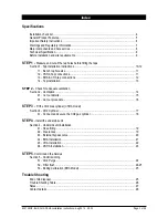
Page 3: ...ections 12 1 4 Tap installation 13 STEP 2 Check for adequate ventilation Section 2 Ventilation 14 2 1 Cut out details 15 2 3 Cut out procedure 16 STEP 3 Fit the CO2 Gas cylinder CSHA model Section 3 C...

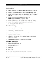
Page 4: ...liance F Check the under counter cupboard supporting the appliance is adequate for the total weight of the appliance when full of water Before Commissioning 1 Check the unit has been installed correct...

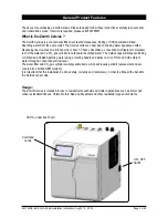
Page 5: ...water and a CO2 gas cylinder to carbonate the chilled water The Celsius taps will dispense Boiling or Chilled and Chilled Sparkling water using a rotating handle and deliver a mix of Hot and Cold amb...

Page 6: ...ly qualified tradesperson The power cable and power outlet must be in a safe visible position for connection Venting Sometimes steam and or condensed droplets may discharge through a vent outlet at th...

Page 7: ...nits must never be located near or cleaned with water jets 8 Zenith appliances are not to be exposed to the elements of nature 9 Due to the process of continuous improvement Zenith Heaters reserves th...

Page 8: ...with hoses 1 off Undersink Unit with air and water filters 1 off Mains water connection hose Vent Kit 1 x Inlet vent 1 x Outlet vent 9 x Screws 1 x Tee piece for ambient water supply 1 x User guide a...

Page 9: ...e product weight when full of water Sufficient space in the cupboard to install all of the undersink units in accordance with these Installation Instructions Refer to technical specification for dimen...

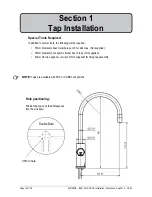
Page 10: ...diameter sheet metal hole punch for sink tops Not supplied 35mm diameter hole saw for timber bench tops Not supplied 42mm AF tube spanner or wrench Not supplied for fixing tap assembly Section 1 Tap I...

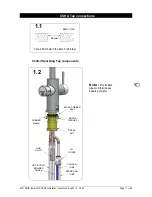
Page 11: ...le in the bench sink top BENCH TOP 1 1 35mm HOT COLD BRAIDED HOSES CHILLED TUBE BRASS WASHER BLACK RUBBER Seal BRASS NUT USB PLUG SPARKLING TUBE JG Y PIECE Note Trim all silicon tubes to minimise any...

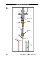
Page 12: ...HA CSHA Installation Instructions Aug 2015 V2 00 HOT COLD BRAIDED HOSES BOILING or CHILLED TUBE BRASS WASHER BLACK RUBBER SEAL BRASS NUT VENT TUBE USB PLUG 1 3 BHA and CHA Tap connections RUBBER Washe...

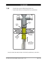
Page 13: ...m hole Ensure the black rubber seal is correctly positioned to give a water tight seal FIT THE RUBBER WASHER BRASS WASHER AND LARGE NUT BLACK RUBBER SEAL 35mm HOLE IN BENCH TOP 1 4 Secure the rubber b...

Page 14: ...e and 300mm above of the undersink unit It is important that the 4mm door buffers For all installations are fitted to the inside edge of the cupboard door to allow suficient air circulation inside the...

Page 15: ...or higher the inlet vent See Item B below and silicon buffers need to be fitted If the airflow is still insufficient to maintain normal operating temperatures then the door outlet vent See item D bel...

Page 16: ...let vent 1 Mark out and cut the air inlet and door outlet holes as shown 2 Ensure the air inlet vent and air outlet vent are positioned at opposite ends of the same cupboard space 3 Fit the inlet vent...

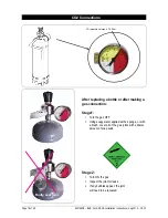
Page 17: ...gas ON rotate the regulator knob clockwise and adjust to 2 7 3 0 bar 270 300kPa The arrow should sit in the green section of the regulator gauge it should not fall in the red or yellow sections 3 4 T...

Page 18: ...tle or after making a gas connection Stage1 1 Turn the gas OFF 2 Using soapy water applied with a sponge or with a brush cover all of the gas joints with a liberal amount of soap suds Stage 2 1 Turn O...

Page 19: ...ut at an angle 2 Remove any swarf or unwanted material 3 Push the tube into the John Guest fitting making sure all connections to the John Guest fittings are pushed in past the O ring to full depth at...

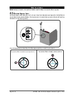
Page 20: ...filter is required 4 3 External Bypass Valve The diverter bypass valve allows the user to choose to have the boiling feed water bypass the internal filter and only be filtered by the external filtrat...

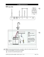
Page 21: ...to the unit RED CLEAR BRAIDED POWER CORD MAINS IN MIXER OUT MIXER IN BOILING OUT BYPASS IN VENT BYPASS OUT USB Note Mains hose length is 750mm Plug and Cord length is 1800mm Position the undersink uni...

Page 22: ...es theTee piece as supplied to be tted in the cold water supply line from the isolation valve Not supplied to the mixer tap See diagrams Note All silicon tubes must be cut to size They must have a con...

Page 23: ...ons Note Trim all plastic tubed to mini mise any dead leg of water Note The Celsius tap require the Tee piece as supplied to be tted in the cold water supply line from the isolation valve Not supplied...

Page 24: ...Filter Flush Mode is in operation Open the filter access door on the front of the unit and the filter cartridge will be exposed Located to the rear RHS of the cartridge is a flush line approx 600mm lo...

Page 25: ...Turn the stop cock OFF then press Stop to end filter flush mode In order to help preserve our environment we ask that you dispose of this product correctly Please contact your local city council for...

Page 26: ...on Call Zenith Service Condenser sensor Open Internal fault Check ventilation Call Zenith service Heater fuse driver fault Internal fault Call Zenith Service Heater driver fault No hot water Call Zeni...

Page 27: ...802149NZ BHA CHA CSHA Installation Instructions Aug 2015 V2 00 Page 27 of 28 Notes...

Page 28: ...9825 and SA2006 08043 Other patents are in force and patent applications are pending As Zenith policy is one of continuous product improvement changes to specifications may be made without prior notic...

Reviews: